Setting up the OptiTrack Tracker
Overview
This tutorial explains how to set up and use OptiTrack as a Tracker in Mimic Core.
OptiTrack is a third party solution. It is used with OptiTrack's software Motive. For in depth documentation of these products, please see the original documentation:
Quick Start Guide: Getting Started (external OptiTrack documentation)
Requirements
This section describes the requirements for using OptiTrack with Mimic Core.
Items needed:
1x Mimic Controller
With Mimic Core (version 1.3 or later)
1x OptiTrack Controller
Includes
Motive version 3
Motive Tracker License
Security Key
Cameras
3x OptiTrack Flex 13 Cameras or more
Camera connection
For Flex 13 Cameras: OptiHub 2
Cables needed:
USB Cable High Grade, Down Angle : e.g. 5 m
(1 unit per Flex 13 Camera)
USB 2.0 Active Extension Cable : e.g. 5 m
USB Uplink Cable, A to B ; e.g. 16 feet
OptiTrack Markers
Minimum 3 Markers to create an object to be tracked as a Tracker and connected with a Joystick.
It is recommended to use a combination of 12.7 and 15.9 mm M4 Markers.
Joystick (custom work)
Joystick to facilitate the Markers needs to be designed.
Nordbo Robotics' has predesigned Joysticks available. Contact Nordbo Robotics for details.
CWM-250 Calibration Wand
Used for calibration in Motive.
Can be purchased directly from OptiTrack or custom made (in accordance with OptiTrack requirements - described further down).
CS-200 Calibration Square
Used for calibration in Motive.
How to Set up
To use OptiTrack as a Tracker in Mimic, both a Mimic Controller and a Windows computer is needed.
This section provides instructions on how to set up these.
Motive - How to Set Up
This section provides an overview of how to setup Motive. For details and full descriptions, please see: Quick Start Guide: Getting Started - (external OptiTrack documentation)
Camera Setup
Connect cameras to the Windows computer running Motive
Using Flex 13: through the OptiHub 2
The connected cameras will show up in motive under “devices”.
Change each individual camera settings to optimize their image quality (focus, exposure time, etc.).
Good result: When markers are visible in Motive, and nothing else.
See guidelines in OptiTrack documentation: Quick Start Guide: Getting Started - (external OptiTrack documentation)
Camera Calibration
Masking
In the top bar, go to View > Camera Calibration Pane
Make sure no reflective markers or other non-static objects are in the scene, and click “Mask Visible”. This will mask out reflections caught by the camera.
Perform "Wanding"
Waving the OptiWand around in view of the cameras.
It is possible to create a custom OptiWand by copying the OptiWand design. See image below
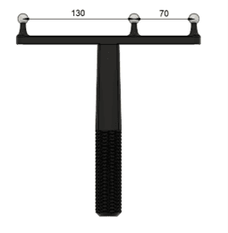
Want Length = 200 mm
Center Distance = 70 mm
Specify these in the Camera Calibration for custom OptiWand in Motive:
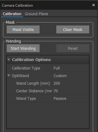
Press “Start Wanding” and start waving the OptiWand in the scene.
Make sure to capture many different positions.
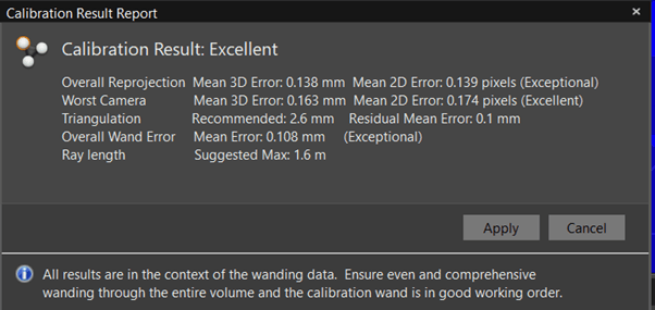
Stop wanding when the software shows green or when around 3000 samples for each camera has been reached. Motive will show a popup indicating whether the calibration was poor or excellent. If poor, then check the measurements of the OptiWand and retry.
Example: The image below shows an “Excellent” alignment
Coordinate Alignment
Coordinate alignment defines the “global reference frame”. This is defined in Motive - and needs to be reflected in Mimic. The usage of Mimic defines this should be done. This section guides you through the needed steps.
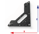
Define Ground Plane in Motive
Click “Ground Plane” in the calibration menu.
Place the alignment plate in the scene and press “Set ground plane”.
The global coordinate system has now been defined.
Mimic Specific Remarks
If you are using Track (or both Track and Teach)
Align the ground plane in the same orientation as the robot base frame.
If you are using Teach
For Teach, the ground plane can have different orientations, as this can be used with Reference Frames in Mimic.
Define a Custom Tracking Object (Rigid Body)
In Motive, a rigid body can be defined. This Rigid body will have a pivot point. When used in Mimic, this pivot point will be the "zero point" to measure from when defining the TCP.
In summary, create a Pivot Point by:
Step 1: Place Markers on hardware
Step 2: Define the Pivot Point
Step 3: Move the Pivot Point to desired location
Step 1: Place Markers on Hardware
Place OptiTrack’s reflective Markers on the object that should be tracked.
● When placing the markers, avid symmetry
● Then define rigid body in Motive
See more here.
Place the object in the scene and select all the markers in Motive > Perspective View.
Right click the markers and select > create rigid body. See image below:
![]()
Note: When you right-click on the points and click "create rigid body", the body will be defined with respect to the ground plane that you set earlier.
Step 2: Define the Pivot Point
The pivot point of the rigid body is the “zero point” of the Mimic Tracker. This is where you measure from, when defining the Joystick TCP.
The pivot point of the rigid body is the center point, but can be changed. It is recommended to use the Probe Calibration method. See Step 3.
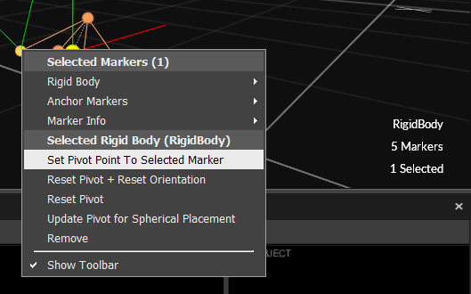
Additionally, it is possible to change the pivot point manually or set to one of the markers by:
selecting the rigid body in the perspective view
then Ctrl click on a marker
right click and set pivot point to that marker
see image below:
Step 3: Move the Pivot Point to desired location
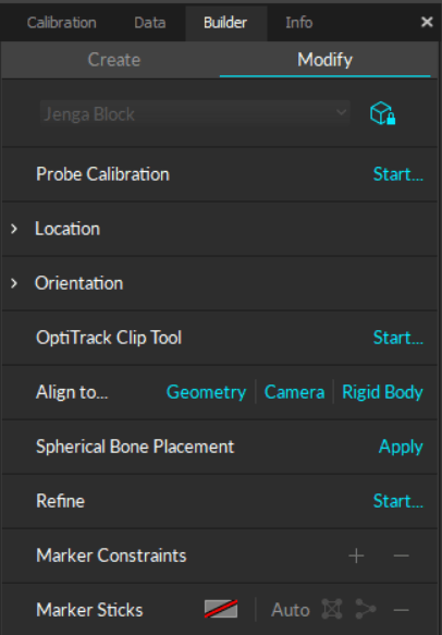
When Step 2 has been completed, the Pivot Point of the Rigid Body is placed between the identified markers. This point is likely not easy to use as a reference for TCP calibration. It can be moved manually as described in Step 2, but it is recommended to use Motive's Probe Calibration method.
This calibration method can be found in Motive's Builder Pane > Modify > Probe Calibration > "Start...".
See details: Rigid Body: Modify
Stream Settings
In Motive top bar, go to Edit > Settings > Streaming
Press the three dots and show advanced settings.
Make sure the settings are set up as shown below:
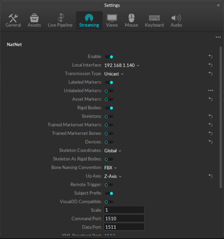
For Mimic Core versions prior to 2.1: set to "Multicast"
For Mimic Core 2.1 or newer: set to "Unicast"
Mimic - How to Setup OptiTrack
Add the Optitrack Tracker in Settings > Tracker
Set as default
![]()
Tracker Settings
The default settings are shown here. Make sure these settings are the same in Motive under “streaming”.
The Server IP Address is the IP address of the server (the Windows PC that is running Motive).
The Client IP Address is the IP address of the client (Controller that is running Mimic).
![]()
Once OptiTrack has been setup, the Tracker status is displayed in the top-right corner. Here, it is also possible to see the amount of markers visible.
You are now ready to use OptiTrack as a Tracker in Mimic!