Custom Joystick / Tracker Mount Settings
Available from version 1.0
Overview
Custom joysticks often bring a lot of value. Let’s say you want to make the standard joystick look more like the tool you have on your robot, or you want to mount the Tracker on an actual tool, then you can create that in Mimic. By the end of this course, you will be able to use Mimic with custom joysticks.
It is important with a good calibration of the joystick to get the correct "translation" between the movements of the joystick and Tracker and the movements of the tool on the robot.
Essentially, we are calibrating a TCP - the point on the joystick that we want to control. So we need to select a point that makes sense to control.
Read more about TCPs here
To add a new joystick, press add, which takes you to a new page. Start out by giving it a meaningful name and adding a comment if needed. For example, name: standard joystick, comment: for demonstrations.”
For the complete setup of the joystick, we need to calibrate both position and rotation.
How to Calibrate
Guidance for performing calibration is provided directly in the interface.
2 calibrations are needed:
Position
Rotation
Position calibration
Position is calibrated by setting 4 points.
The position of the point must be the same, but the orientation of the 4 points must be the same. This means that the joystick should point at the same point for all 4 points, but at different orientations (angles).
The closer the positions from the 4 positions are, the more precise it will be.
Rotation calibration
Rotation is calibrated by:
Defining the origin of the Frame (coordinate system)
Defining the positive x-axis of the robot
Defining the positive y-axis of the robot
The more precise this is performed, the more precise the calibration will be.
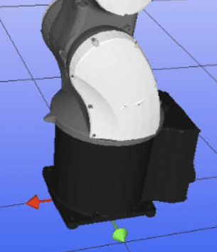
If in doubt of the robot's coordinate system: Go to Settings > Robot > Select the robot, see the axis in simulation.
Example:
NACHI robot with X and Y.
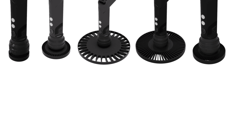
Example of Nordbo Robotics custom joystick
Painting Spray Gun
OEM Mount - Fake Spray Gun (Beta) | 3D CAD Model Library | GrabCAD
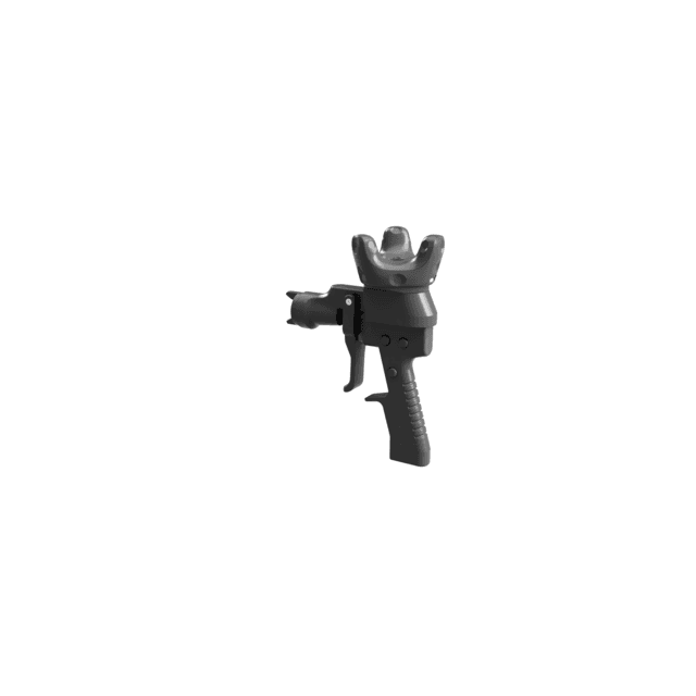
Application Demo Kit for IR Tracker
These are extensions that can be mounted to the IR Standard Joystick, to simulate various surface treatment tools.