Mimic 2.0
New in Mimic Core 2.0
Update to the latest Mimic Core version using the Nordbo Update Tool.
Mimic Core 2.0 represents a significant increment in the software.
A new and more user friendly interface, makes no-code programming even easier than before.
Simulation and programming makes it possible to see the recordings in 3D - and checks for collisions in advance.
Below, you will find a complete list of major additions:
New and improved Creator and Production interface
A design that focuses on ease of use, while supporting new functionality.
New and improved navigation menu
Navigate Mimic from only one menu.
Simulation and Path Planning
Highly requested, Mimic Core now supports a 3D visualization of the paths recorded.
Path Planning enables visualization of the path, and check of collision with 3D models imported into Mimic
Realtime view of tool in Simulation - see where the tool is live.
Collision check
Checking with 3D models of items imported to workcell, robot mount or part.
User Levels
Added two user levels. Operator and Expert.
Operators can select and play programs
Experts can create, modify, play and adjust settings
Point to Point in Teach
Create point to point recordings in Teach
New features in Edit
Added the option to apply constant speed for whole trajectory
Added the option to apply max speed for whole trajectory
Added the option to apply force for whole trajectory (requires a Nordbo Active Compensation Unit (NAC) or a force sensor in a UR eSeries robot)
Added speed scale parameter to recording
Sub-programs called from robot
In Library, call a program from the robot. E.g.:
Home position
Call another component
Adjust speed when going to Home Position
In Settings, define the speed at which the robot should move to the Home Position.
Note: Only available on FANUC and NACHI in 2.0.
OptiTrack specific - see number of markers visible
OptiTrack uses markers to track the Tracker. Now, it is possible to see status informing about amount of visible markers in topbar notifications.
New calibration method of Frames
A new calibration method for calibrating Frames has been added to enable calibrations with higher precision.
Support additions
Added support page with export options for support data.
Added debug mode in settings. When enabled, additional information is provided in log.
Important remarks
Prior to updating to 2.0, it is recommended to make a backup.
Mimic Core 2.0 is not backwards compatible. Simulation and Offline Planning requires a different approach to handling recordings and programs. Hence, programs made with 2.0, cannot be executed on earlier versions.
It is possible to run old recordings and programs on 2.0.
French language not available in 2.0.
2.0 comes with a few items to be aware of. See the list below:
Minor UI implementations are being revised
2.0 introduces the new feature "Adjust speed when going to Home Position". It has been observed that this is not fully compatible with Nachi robots. Here, the robot will move slowly to the Home Position, regardless of the speed set.
Conveyor tracking is not considered functional.
These items are being addressed and will be resolved in the released version.
Getting to Know Mimic
Mimic is a software platform that uses a tracking device to track the user’s movements, enabling the user to record and replicate complex movements that are challenging to automate with robots. Mimic records both position and orientation, drastically reducing the time spent programming and reprogramming a robot. Mimic is a dedicated software platform, that can be integrated with any of the robot brands described in this documentation works together with a Tracker from Nordbo Robotics.
Mimic gives the user the following 3 main steps to create a recording:
1. Record
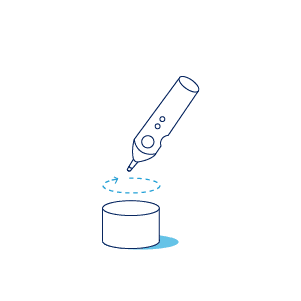
2. Edit (if needed)
3. Play
Scoping
Usage
Mimic is an easy-to-use platform that allows anyone to record and automate tasks without any prior programming experience. With Mimic, you can simply record, transfer, and replicate your own movements, making automation easier than ever before.
By implementing a Mimic system together with your robotic integration you remove the need to spend hours programming your robot to complete simple tasks. With minimal experience any operator will be able to learn how to utilize the software and teach your robot via one of our tracking technologies.
Installation and Setup
While using Mimic does not require much robotics expertise, installation and setup requires, especially with integration into production equipment, requires a technical profile and experience with robots and the equipment used.
Nordbo Robotics' Workshop is an online platform that provides documentation for both Usage and Installation and Setup.
Overview of Mimic Core 2.0 Structure
Overview
The main building blocks in the Mimic Core software platform are:
Home/Mimic, where you can access everything and create new recordings in the Creator space
These can be either Track or Teach, but more on that later
Creator, where you can create programs (Track, Teach, Path Generator or Sander)
Library, where all of of your recordings are listed and where you can create complete programs.
Production, where you can select and run existing programs
Settings, where you can tailor Mimic to your setup
Support, an integrated support page.
Notifications, (top-right corner) where you see status on connectivity to the robot and Tracker
User Levels, (top right corner) specifying user permissions.
Important! As the User Level specifies the permissions, it is important to check whcih is enabled.
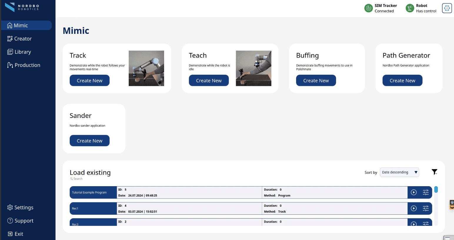
Home
Home is the first page you land on after installing Mimic Core.
This is where you can see which recording methods and Mimic add-ons are available for you.
Creator Page
Creator page is where you can record and edit movements. You can simply record a motion and play it right away. If needed, there are several features that you can use to get the recording you want. Depending on the method selected, Track, Teach or Path Generator the functions and the features differ.
Settings
Settings page guides you through the setup of hardware and software to tailor Mimic for your needs and to work efficiently when capturing and running movements. Under settings you will find all the pages needed for setting up and calibrating your
System
Robot
Tracker
Tracker Mounts (previously named Joystick)
Robot Mounts (previously named Robot Tools)
Inputs and outputs mapping
Workcell
Components
Frames
Notifications
Notifications give you a quick overview, showing if the Tracker and the Robot are connected or not.
Library
Library is where you can find all of your recordings. Here you can also stack your recordings in a complete program, and run them together
What you need prior to Mimic installation
Full HD touch monitor (1080p) (22" is recommended) with mouse and keyboard
Gigabit switch (optional - needed if connecting other hardware to the robot)
Ethernet cables long enough to reach from your teaching station to the robot
Recommendations for powder coating setups
When selecting a monitor for powder coating setups, we recommend using and industrial monitor with IP65 and ATEX / IECEx Zone22.
The Mimic Controller
The Mimic Controller is where the Mimic software runs.
To set it up:
Connect the power supply to the Mimic Controller
Connecting the Mimic Controller to the robot (see robot specific tutorials for specific guidance)
Depending on what kind of setup you are planning, you might need to connect the Mimic Controller with the Gigabit switch using the ethernet cable, if for example, you will need to connect more hardware.
Important Notice on System Integrity
To ensure full compatibility and stable operation, please only update the software provided by Nordbo Robotics. Updating the operating system or other third-party software may interfere with system performance or disrupt critical integrations.
UR Preparation
In this course you will learn how to prepare robots from Universal Robots (UR) for using Mimic.
Please note that precision of the use of the robot with Mimic is dependent on the calibration of the robot itself. Not all robots are calibrated by default to satisfy all application requirements. Please check the calibration of the robot prior to use.
Mimic for UR - Robot Preparations
Mimic is compatibe with Universal Robots' Polyscope versions:
CB Series: 3.14.3 or newer
eSeries: 5.9.4 or newer
Mimic is compatible with all UR robot models running Polyscope 5.
Please see Mimic Controller Setup to see what is needed for the Controller setup.
Mimic for UR - Get started
To install Mimic on a UR robot, see the following steps. These will guide you through
How to setup robot and its network network
How to install the URCap needed
How to setup Mimic Controller and Nordbo Driver network
How to create the main UR program
Note: The robot code needed (incl. the URCap) is on the USB in the package. It is always possible to get the latest robot code on Nordbo Update Tool, ⬇️ Software Download.
Setup Robot Network
In this section you will find what you need to setup the network on the robot to enable communication with the Mimic Controller. This includes:
The robot
The Nordbo Driver (URCap)
The Mimic Controller
The IPs provided are recommended defaults. They can be changed if needed. If changed be aware that the IP on the Mimic Controller and the IP specified in the Nordbo Driver URCap must be the same.
Change the IP of the Robot:
To change the IP on a UR, go to Settings > System > Network > IP address
Change the IP of the UR to a static IP (default IP 192.168.1.50)
Set the net mask to 255.255.255.0
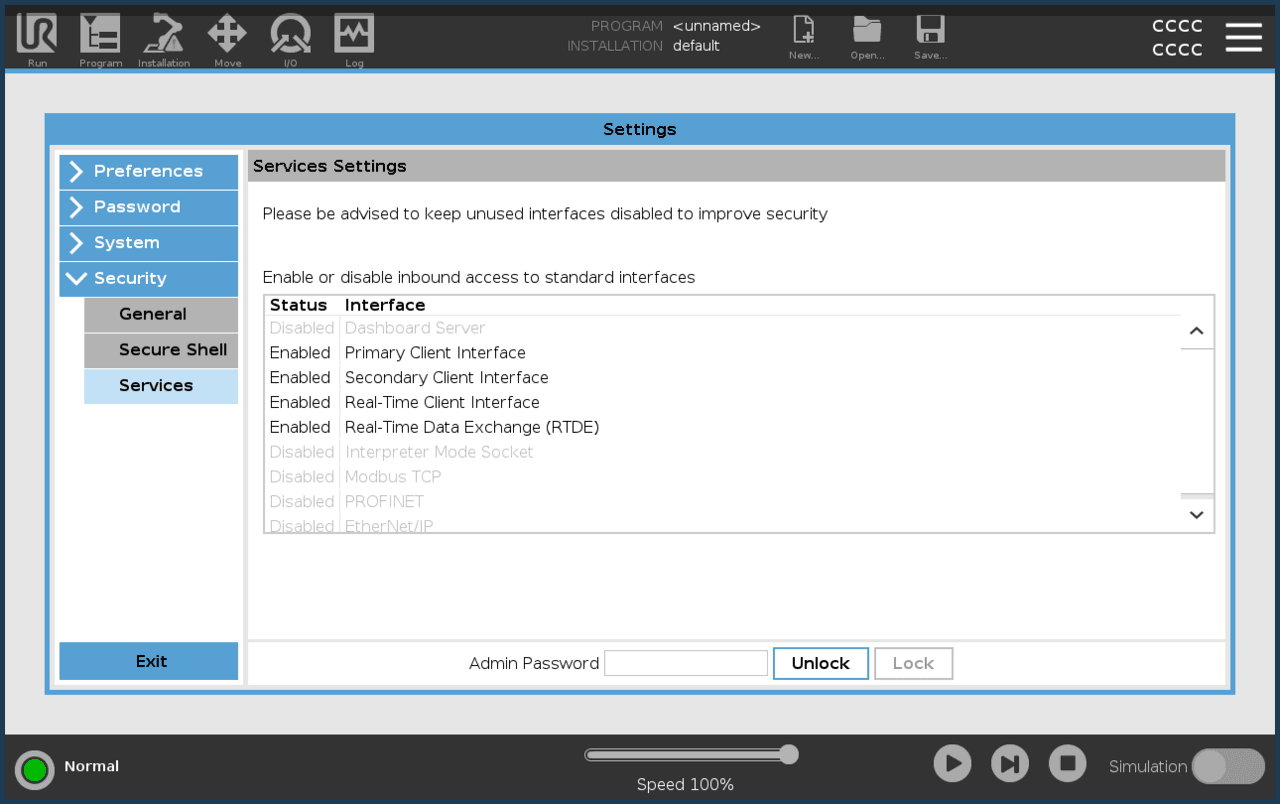
UR Services Needed
In order for Mimic Core to communicate with UR robots, the following services need to be enabled:
How to Install the URCap Needed and Setup Mimic Controller and Nordbo Driver
Step 1. Insert the USB with the URCaps into the robot Teach Pendant and install the Nordbo Driver URCap
Note: The Nordbo Driver URCap needs to be version 2.4
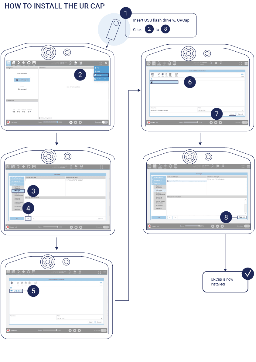
Step 2. Enable the Nordbo Driver and set the Nordbo Driver IP
Go to Installation > Nordbo Driver
Enable the Nordbo Driver by toggling the checkbox
Insert the Mimic Controller IP: 192.168.1.20 (default)
Note: The IP can be changed but needs to be the same as the Mimic Controller provided in the box.
Press "Update" to finish
Save the UR Installation File ("Save..." > "Save UR Installation File...")
How to Create the Main UR Program
There are 2 scenarios for using Mimic on a UR robot:
Control the robot from Mimic (most common use)
Controlling the robot from Mimic means Mimic is given control of the robot. Hence, Mimic functionality is accessed through the Mimic interface.
E.g. to use Mimic's Track, the user can navigate to the Track page, directly in the Mimic interface.
Control Mimic from the robot (advanced use for production)
Controlling Mimic from the robot means the robot remains in control and can call Mimic functionality. Hence, Mimic functionality is accessed through the robot.
E.g. to use Mimic's Track, the robot will call the Track functionality in Mimic and change the Mimic interface to the Track page.
How to create UR programs for each of these scenarios is described in this section.
Control the robot from Mimic
To enable the control of the robot from Mimic, setup the program as shown in the picture below.
Note: The UR program must be running, to use both Record and Edit. It does not need to be running for Recording.
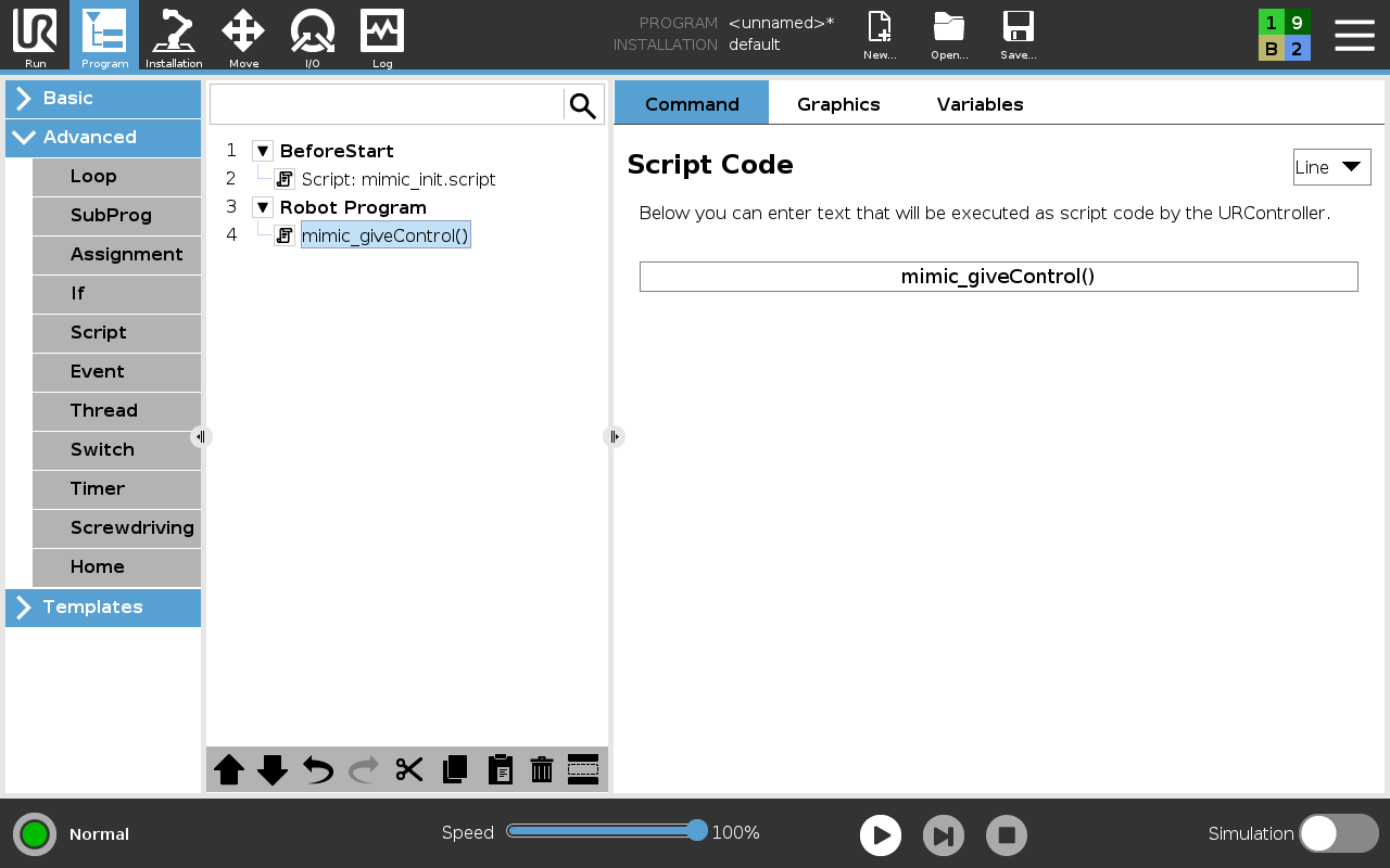
Control Mimic from the robot
Use the Script: mimic_init.script in BeforeStart.
2 scripts are available to use Mimic functionality:
track_mimic_program( )
Calls Track functionality in Mimic.
run_mimic_program( )
Calls Run functionality in Mimic.
The number specified in ( ) is the ID of the program. Only predefined programs in Mimic can be called. See example below.
The scripts can be used multiple times in the program. See example below.

Example: A UR program that calls a Track program with ID 12 and Run program with ID 12
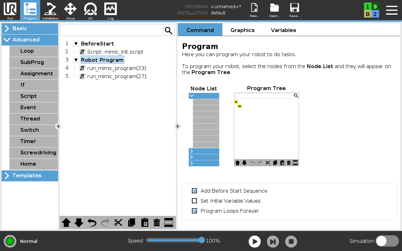
Example: A UR program that calls a Run program with ID 23 and another Run program with ID 27
Explainer: I/O mapping from Mimic to UR
The I/O belonging to Mimic is mapped to the I/O of the UR robot. This mapping is shown below:
Inputs:
Robot[0-7] -> Digital Inputs[0-7]
Robot[8-9] -> Tool Digital Inputs[0-1]
Robot[10-17] -> Configurable Inputs[0-7]
Outputs:
Robot[0-7] -> Digital Outputs[0-7]
Robot[8-9] -> Tool Digital Outputs[0-1]
Robot[10-17] -> Configurable Outputs[0-7]
Using sub-routines with Mimic on UR
To use subroutines on the UR robots, some modifications need to be made to the robot program.
The subroutine functionality is facilitated using the registers nrhw_int_reg[3] and nrhw_int_reg[4].
The nrhw_int_reg[3] register holds a bit value which indicates if a subroutine should be called
The nrhw_int_reg[4] holds the ID of the subroutine.
An example of how this can be implemented is shown below:
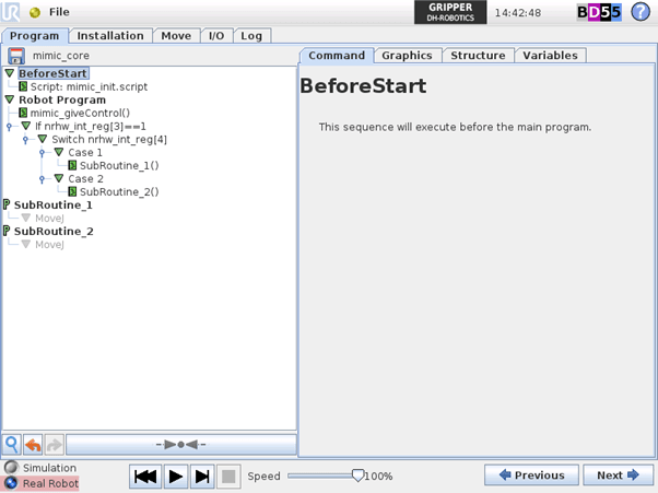
Where SubRoutine_1 and SubRoutine_2 are user defined programs
Your UR robot is now ready to use Mimic.
Nachi Preparation
In this course you will learn how to prepare robots from Nachi for using Mimic.
Please note that precision of the use of the robot with Mimic is dependent on the calibration of the robot itself. Not all robots are calibrated by default to satisfy all application requirements. Please check the calibration of the robot prior to use.
Mimic for Nachi - Robot Preparations
Mimic Core is compatible with the follwoing Nachi Controllers:
FD Controller (external tracking card needed)
CFD Controller (external tracking card needed)
CFDs Controller
CFDq Controller
What you need prior to Mimic installation
External tracking module (Nachi external tracking card - only applicable for FD and CFD Controllers)
The Nachi controller supports: Intel PWLA8391GT PRO 1000GT Network Card Ethernet PCI RJ45 (or other card with Intel PWLA8391GT).
Gigabit switch (at least 3 ethernet ports)
Ethernet cables (2 extras)
Please see: Mimic Controller Setup
Known unsupported models
CZ10
All Nachi cobots
Note: The robot code needed is on the USB in the Mimic package. It is always possible to get the latest robot code on Nordbo Update Tool, ⬇️ Software Download
Hardware Setup
Connect a Gigabit switch to the Mimic Controller connect 2 ethernet cables to the switch and the robot.
Wire the Mimic Controller to the Robot
Install the external tracking network card.
Connect the switch to the Mimic Controller
Connect the 2 ethernet cables to the switch and the robot
- One from the external tracking network card to the switch
- One from the main network card to the switch
Restart the robot.
How to Configure a Nachi Robot
Login and Change the Permission on the Robot
Change the permission on the Nachi robot to the specialist level.
Press “R” on the teachpad,
enter the code “314”,
press “Enter”,
enter the code “12345” and
press “Enter”
Disable Memory Protection
Change permission on the robot to be "specialist"
Navigate to “Constant Setting” > “1 Control Constants” > “11 Memory Protection”.
Hold down the physical Enable button on the teachpad and switch the memory protection to “Disabled”.
Click on “Complete” to save the changes.
Restart the robot.
Setup the Extend Ethernet
Change permission on the robot to be "specialist".
Navigate to “Constant Settings” > “8 Communications” > “7 Extend Ethernet”.
Set extend ethernet to “Enabled”, the IP address to 192.168.1.51 (default) and the Subnet mask to 255.255.255.0.
Note: The IP address can be different from the default but need to be on the same subnet as the Mimic Controller.
Press “Complete” to save the change.
Restart the robot.
Enable Memory Protection
Change permission on the robot to be "specialist".
Navigate to “Constant Settings” > “1 Control Constants” > “11 Memory Protection”.
Hold down the physical Enable button on the TeachPad and switch the memory protection to “Enabled”.
Press on “Complete” to save the changes.
Restart the robot.
Setup the External Tracking
Change permission on the robot to be "specialist".
Navigate to “Constant Settings” > “45 External Tracking”.
Set the IP address to 192.168.1.20.
Set the Port to 2568,
User(Digital) inputs: This is set to the start index of which inputs Mimic can read. Mimic reads 64 inputs so if the index is set to 21 it will read the inputs 21 - 84. Setting this index to 0 will prevent Mimic from reading any inputs.
User(Digital) outputs: This is set to the start index of which outputs Mimic can set. Mimic sets 64 outputs so if the index is set to 21 it will set the outputs 21 - 84. Setting this index to 0 will prevent Mimic from setting any outputs.
Set Timeout to 300 ms.
Set Parallel movement 0.0mm, 0.0mm.
Set Rotational movement 0.00deg, 0.00deg.
Set Joint angle to 0.00deg.
Press complete to save
Restart the robot.
Setup the Main Ethernet Connection
Change permission on the robot to be "specialist".
Navigate to “Constant Settings” > “8 Communications” > “2 Ethernet” > ”1 TCP/IP”
Hold down the physical Enable button on the Teachpad and change the DHCP to “Disabled”
IP to 192.168.1.50.
The IP address can be different from 192.168.1.50, but it needs to be the same as the subnet on the Mimic Controller and the IP for the Extend Ethernet.
Subnet mask to 255.255.255.0.
Press complete to save.
Restart the robot.
Transfer Mimic Program to the Robot
Transfer the robot programs to the robot in the “Program” folder.
This can be achieved using ftp. The files can be found on the USB.
FTP (Optional)
Change permission on the robot to be "specialist".
Enable FTP. Navigate to “Constant Settings” > “8 Communications” > “2 Ethernet” > ”3 FTP” Change FTP Service to “Enabled”.
Connect a PC to the robot via ethernet cable.
Open a file browser
Go to ftp://192.168.1.50
You should now be able to add files to the robot by using the file browser. Add them to the program folder.
Restart the robot.
The files to transfer are:
Change the filenames of MZ07-A.*** to the robot model used
Example: If using a MC20 the MZ07-A.000 file needs to be named MC20-A.000.
Public.inc (Global variable definitions)
USERTASK-A.000 (TCP communication with Mimic Controller)
USERTASK-A.001 (UDP communication with Mimic Controller)
GLOBALCONST.INC (Global numeric constants variable definitions)
INSTRUCTIONSERVER.INC (Numeric constants and variable alias for USERTASK-A.000)
LOGSERVER.INC (Numeric constants and variable alias for USERTASK-A.001)
GENERALSERVER.INC (Numeric constants for USERTASK-A.000 and USERTASK-A.001)
BOXCOMMANDS.INC (Numeric constants for USERTASK-A.000 and MZ07-A.000)
VARIABLEALIAS.INC (Variable alias names for MZ07-A.000 and MZ07-A.001)
MZ07-A.000 (Robot Program for execution of Mimic Controller commands)
MZ07-A.001 (Robot Program for execution of Mimic Controller trajectories)
MZ07-01-A.002 (Robot Program to Run Robot Sub-routines. See details further down)
MZ07-A.072 (Mimic main program)
MZ07-A.071 (Example on how to play a Mimic program from the robot. Calls program 70)
MZ07-A.070 (Program 70)
MZ07-A.081 (Example on how to start Track from the robot. Calls program 80)
MZ07-A.080 (Program 80)
MZ07-A.091 (Example on how to start Teach from the robot. Calls program 90)
MZ07-A.090 (Program 90)
MCC_LOCALVARS.INC (Local variables for MZ07-A.000)
USERTASK0_LOCALVARS.INC (Local variables for USERTASK-A.000)
Restart the robot.
All the included files are only loaded after robot restart.
Compile the robot programs
Change permission on the robot to be "specialist".
Navigate to “Service Utilities” > “9 Program Conversion” > “8 Language”.
Select the robot programs to compile.
USERTASK-A.000
USERTASK-A.001
MZ07-A.000
MZ07-A.001
MZ07-01-A.002
MZ07-A.070
MZ07-A.071
MZ07-A.072
MZ07-A.080
MZ07-A.081
MZ07-A.091
MZ07-A.090
Restart your robot.
Using sub-routines with Mimic on NACHI
It is possible to call sub-routines from the Robot when creating a complete Program in Mimic's Library. See Library.
To do this on Nachi, use the provided Robot Program MZ07-01-A.002. This is a switch case.
The "Case number" corrosponds to the program ID used in the Mimic Program (created in the Mimic Library). Hence, if the Mimic sub-routine ID = 1, the Nachi Robot Program runs CASE 1.
REM "Run robot job"
INH
SWITCH A1!
CASE 1
(write code here)
BREAK
CASE 2
(write code here)
BREAK
CASE 'Nothing
BREAK
ENDS
END
It is possible to write the intended behaviour directly in the CASE. It is also possible to call an existing NACHI program on the robot.
Example: Calling existing NACHI program with number 30, in CASE 1:
REM "Run robot job"
INH
SWITCH A1!
CASE 1
CALLP 30
BREAK
CASE 2
BREAK
CASE 'Nothing
BREAK
ENDS
END
Your Nachi robot is now ready to use Mimic.
KUKA Preparation
In this course you will learn how to prepare robots from KUKA for using Mimic.
Please note that precision of the use of the robot with Mimic is dependent on the calibration of the robot itself. Not all robots are calibrated by default to satisfy all application requirements. Please check the calibration of the robot prior to use.
Mimic for KUKA - Robot Preparations
KUKA robots are controlled with the RobotSensorInterface (RSI) 4.0 option package (tested with 4.0.8). Ensure that the RSI package is installed on KUKA robot before you install Mimic. This module can be acquired from Kuka together with a manual on how to install it.
You will need the KUKA controller version = KSS 8.5.
Note: Setting the payload that matches the actual payload on the robot is always important. KUKA robots sets higher requirements for this when using Mimic. If an imprecise payload is set, this will effect the performance.
Note: The robot code needed is on the USB in the Mimic package. It is always possible to get the latest robot code on Nordbo Update Tool.
Hardware Setup
Complete the Tracker Hardware Setup before this step.
Please see Mimic Controller Setup to see what is needed for the Controller setup.
Wire the Mimic Controller to the Robot
Step 1. Connect the ethernet cable to the Mimic Controller
Note: (Optional) Use a Gigabit switch.
Step 2. Connect the ethernet cable to the robot
Mimic for KUKA - Get started
How to Configure a KUKA Robot
Step 1. Change permission to administrator level
Start by changing the permission on the Kuka robot to administrator level.
This is achieved by:
Starting up the robot
Clicking on the “user” symbol in the left sidebar on the left side of the teach pendent
Inside the user page, click on “Administrator” and enter the code “kuka” and click on “Login”
Step 2. Setup the IP address of the RSI
See the RSI manual to see how to change the IP of the RSI.
The IP address of the RSI and the Mimic Controller have to be on the same subnet, e.g. 192.168.1.XX.
The IP address of the RSI can be changed as described in the RSI manual.
Press on the Robot icon in the top left corner of the teach pendant.
Press on “Start-up” > “Network Configuration” > “Advanced” > “Add Interface” > Choose a name for the Interface > Choose "Mixed IP address" and set the IP to 192.168.1.50 (default).
The IP can be changed but needs to be on the same subnet as the Mimic Controller.
Set the net mask to 255.255.255.0
Note: if the IP of the Mimic Controller has been changed, it needs to be changed in the RSI_mimicConfig.xml file as well. See next section.
Transfer Files to the Robot
Transfer the supplied files to the robot. This can be achieved using WorkVisual or transfer them directly from USB. The files can be found on the USB.
RSI file should be transferred to "C:/KRC/ROBOTER/Config/User/Common/SensorInterface” and program files should be transferred to “KRC/R1/Program”.
How to transfer program files with USB (Optional)
Insert the USB into the robot controller
To see the USB, change the user to Administrator (see step 1)
Select the files from the USB
Click Edit > Copy
Select the destination folder
Click Edit > Paste
The files to transfer are:
RSI_mimic.rsix
RSI structure
Location: RSI folder
RSI_mimicConfig.xml
UDP communication config
Location: RSI folder
Note: if the IP of the Mimic Controller has been changed, it needs to be changed in this file as well.
Ncom.dat
General mimic functions
Location: Program folder
Ncom.src
General mimic functions
Location: Program folder
Mimic.dat
Example of a mimic program
Location: Program folder
Mimic.src
Example of a mimic program (e.g. Track, Teach and Play)
Location: Program folder
I/O Mapping
In Mimic, it is possible to use 64 robot inputs and 64 robot outputs. The inputs and outputs used in Mimic are mapped to:
Digital inputs 65-128
Digital outputs 65-128
If needed experts can change this mapping in WorkVisual or in the RSI file "RSI_mimic.rsix".
Your KUKA robot is now ready to use Mimic.
Fanuc Preperations - Stream Motion
For Mimic Core 1.3 and 2.0
In this course you will learn how to prepare robots from FANUC for using Mimic with Stream Motion.
Please note that precision of the use of the robot with Mimic is dependent on the calibration of the robot itself. Not all robots are calibrated by default to address all application requirements. Please check the calibration of the robot prior to use.
Mimic is compatible with FANUC robots. Be aware that:
FANUC's PaintTool is incompatible with FANUC's Stream Motion. Hence, making Mimic incompatible with PaintTool.
The performance of Stream Motion is dependent on the $SRC.$ITP_TIME value of the FANUC robot.
If issues arise with Stream Motion, such as but not limited to jerk limit errors, ensure that the $SRC.$ITP_TIME is set correctly.
A value of 8 ms performs well in most cases.
The $SRC.$ITP_TIME setting can be found in the robot controller pendant, under System > Variables.
What you need prior to Mimic installation
Please see Mimic Controller Setup to see what is needed for the Controller setup.
Stream Motion (J519), User Socket Messaging (R648) and Remote Motion Interface (R912) version 4.0 (FANUC specific)
FANUC Controller
RMI requires a controller of type R-30iB Plus (hardware)
The software version on the controller must be V9.30P/31 or newer
KAREL (R632) package for FANUC
FANUC Controllers has different ethernet ports: A, B and C. Port C is dedicated to FANUC, and no external equipment can be connected to this. Hence, Mimic cannot be connect to port C, but should be connected to A or B.
FANUC robots are controlled by Mimic with the Stream Motion (SM) and Remote Motion Interface (RMI) optional packages. Additionally, the User Socket Messaging (USM) is used for communication between the Fanuc robot and Mimic. Ensure that the SM, RMI and USM packages are installed on the FANUC robot before you install Mimic.
These modules can be acquired from FANUC.
Note:
The FANUC Driver for Mimic is developed for RMI version 4.0. Backwards compatibility is not guaranteed.
Mimic for FANUC includes compiled KAREL programs which are used to interface with the robot I/O. These can run on the robot without the need of any additional modules. If it is desired to change which I/O or registers are used by Mimic, the included source code files have to be modified and compiled. To compile the source files, the ROBOGUIDE software from Fanuc can be used. Alternatively, the KAREL option can be used to compile the source files locally on the robot.
The robot code needed is on the USB in the Mimic package. It is always possible to get the latest robot code on Nordbo Update Tool.
Mimic for FANUC - Robot Preperations
Hardware Setup
Complete the Tracker Hardware Setup before this step.
Wire the Mimic Controller to the Robot
Step 1. Connect the ethernet cable to the Mimic Controller
Note: (Optional) Use a Gigabit switch.
Step 2. Connect the ethernet cable to the robot
Mimic for FANUC - Get started
How to Configure a FANUC Robot
Step 1 Setup the IP address of the FANUC robot
The IP address of the FANUC robot and the Mimic Controller have to be on the same subnet, e.g. 192.168.1.XX.
The IP address of the FANUC robot can be configured as following:
Press the “MENU” button on the teach pendant
Select “6 SETUP “, navigate to the 3rd submenu titled “Setup 3” and choose “4 Host Comm” and press the “ENTER” button on the teach pendant
Select “1 TCP/IP” and press the “ENTER” button on the teach pendant.
Set the IP address in the field titled “Port#1 IP addr:”
Set the Subnet Mask to “255.255.255.0”
If preferred, the IP address of the Mimic Controller can be changed through the Mimic software.
Press the “SETTINGS” button from the home page of the Mimic software
Press the “NETWORK” tab from the settings page to enter the network settings page.
Manually configure the IP address by setting the network mode to “STATIC” and enter the desired IP address and subnet mask in the “IP” and “Subnet” fields.
Alternatively, the “DHCP” network mode can be chosen, to let the Mimic controller receive an IP address automatically. Note that an IP address will only be assigned if a DHCP server is present on the network.
Press the “Save” button in the bottom right corner of the network settings page to apply the settings.
Step 2 Enable RMI JSON format instructions
Mimic sends instructions to the FANUC robot using the JSON format, which needs to be enabled on the robot.
This can be enabled as follows:
Press the ”MENU” button on the teach pendant
Select “0 -- NEXT --” and press the “ENTER” button on the teach pendant to go to “MENU 2”
Select “6 SYSTEM” and then Select “2 Variables” and press the “ENTER” button on the teach pendant.
Select the variable titled “$RMI_CFG” and press the “ENTER” button on the teach pendant
Select the variable titled “$ASBN_ENB” and press the “FALSE” or “F5” button on the teach pendant.
Step 3 Configure Stream Motion
To ensure that Stream Motion is configured correctly for Mimic, ensure that the following settings have been set as described:
Press the ”MENU” button on the teach pendant
Select “0 -- NEXT --” and press the “ENTER” button on the teach pendant to go to “MENU 2”
Select “6 SYSTEM” and then Select “2 Variables” and press the “ENTER” button on the teach pendant.
Select the variable titled “$CPCFG” and press the “ENTER” button on the teach pendant to enter the configuration
Select the variable titled “$CP_ENABLE” and set it to “TRUE”
Press the “PREV” button on the teach pendant to go back to the variables list
Select the variable titled “$PARAM_GROUP” and press the “ENTER” button on the teach pendant to enter the configuration
Select the variable titled “$SV_OFF_END” and set them all to “FALSE”
Press the “PREV” button on the teach pendant to go back to the variables list
Select the variable titled “$STMO” and press the “ENTER” button on the teach pendant to enter the configuration
Select the variable titled “$START_MOVE” and set it to 5
Press the “PREV” button on the teach pendant to go back to the variables list
Select the variable titled “$STMO_GRP” and press the “ENTER” button on the teach pendant to enter the configuration
Select the variable titled “$FLTR_LN ” and set it to 100
Press the “PREV” button on the teach pendant to go back to the variables list
Additional Notes:
Ensure a precise load weight is specified, as this will help prevent acceleration errors
The “$MAX_SPD” value under the “$STMO_GRP” variable can be increased to increase the upper acceleration limit.
Step 4 Enable HTTP access to KAREL code on the FANUC robot
Mimic needs access to run KAREL programs on the FANUC robot through an HTTP connection.
This can be enabled as follows:
Press the “MENU” button on the teach pendant
Select “6 SETUP“ and navigate to the 3rd submenu titled “Setup 3” and select “4 Host Comm” and press “ENTER” on the teach pendant
Select “7 HTTP” and press the “ENTER” button on the teach pendant to enter the “HTTP Setup” menu.
Select the row which says “KAREL:*" in the column titled “RESOURCE”.
Select the first column on the furthest left, with a field saying either L, U or A. Press the “UNLOCK” or “F3” button on the teach pendant, the field should now say U for unlocked.
Transferring Files to the FANUC robot
Transfer the supplied files to the robot, this can be done directly through USB.
The files can be found on the USB.
How to transfer program files with USB
Insert the USB into the teach pendant
Press the “MENU” button on the teach pendant
Select “7 File” then select “1 File” in the subsequent submenu and press the “ENTER” button on the teach pendant
Press the “[UTIL]” or “F5” button on the teach pendant
Select “1 Set Device” and press the “ENTER” button on the teach pendant.
Navigate to the 2nd submenu, select “1 USB on TP (UT1:) “ and press the “ENTER” button on the teach pendant.
To list all files on the USB, select line 1 from the selection, titled “(all files)” in the rightmost column and press the “ENTER” button on the teach pendant.
Navigate to the file desired for transfer to the robot and press the “LOAD” or “F3” button on the teach pendant. Press the “YES” or “F4” button on the teach pendant to transfer the file.
The files to transfer are:
updateio.pc - Interface between Mimic and robot I/O
mapio.tp - Mapping of robot I/O used by Mimic
getregister.pc - Get robot register value in Mimic
setregister.pc - Set robot register value from Mimic
STREAM_MOTION.TP - TP-program used to start Stream Motion
mimic_play.pc - Start Mimic recording from robot
mimic_track.pc - Open Mimic track recording from robot
mimic_teach.pc - Open Mimic teach recording from robot
mimic_give_control.pc - Used to indicate when Mimic can take control of the robot
Be aware that two additional files are supplied, named “updateio.kl” and “MapIO.ls”. These are the source code files of “updateio.pc” and “mapio.tp”, which will be needed if changing the I/O or registers used by Mimic is desired. The KAREL option is needed here.
Note that if you are updating an existing installation, it will not be possible to transfer the newest version of the “mapio.tp” file, as it will be running as background logic on the robot. To stop the current “mapio.tp” program, follow these instructions:
Press the “MENU” button on the teach pendant.
Select “6 SETUP” and navigate to the 2nd submenu titled “SETUP 2” and select “6 BG Logic” and press “ENTER” on the teach pendant.
Navigate to the row containing “MAPIO” in the “PROGRAM” column and press the “STOP” or “F3” button on the teach pendant.
The program has now been stopped as background logic and can be updated. Remember to start the program as background logic again, after it has been updated.
Starting background tasks on the FANUC robot
Mimic uses the “updateio.pc” KAREL program on the FANUC robot to interface with the robot I/O. This is done by reading from and writing to the last 32 registers on the robot and using the “mapio.tp” as background logic to map these registers to the desired inputs and outputs. The last 32 registers, I.e., registers 169 to 200 should be seen as reserved by Mimic. The “mapio.tp” program can be started as background logic as follows:
Press the MENU button on the teach pendant
Select “6 SETUP“ and navigate to the 2nd submenu titled “Setup 2”, select “6 BG Logic” and press the “ENTER” button on the teach pendant
Move to a row where the entry on the “PROGRAM” column is empty
Press the “[CHOICE]” or “F4” button on the teach pendant
Find “MAPIO” from the list and press the “ENTER” button on the teach pendant Note: If “MAPIO” is not on the list, try transferring the “mapio.tp” file to the robot again
To start the program, press the “RUN” or “F2” button on the teach pendant.
Setting up digital IO on Fanuc
In order to use digital IO on the Fanuc robot, the appropriate I/O needs to be assigned.
Assigning digital I/O
Press the MENU button on the teach pendant
Select “5 I/O” and navigate to the 1st submenu titled “I/O 1” and select “5 Digital” and press the “ENTER” button on the teach pendant.
Press the “CONFIG” or “F2” button on the teach pendant.
Configure the “RANGE” as “[1-8]” and set the appropriate “RACK”, “SLOT” and “START” values based on the I/O interface.
In case digital I/O are unused, values “0”, “0”, “1” should be chosen for “RACK”, “SLOT” and “START”.
Press the “IN/OUT” or “F3” button on the teach pendant, to switch between the configuration pages for inputs and outputs.
Repeat steps 4 and 5 again, to configure the remaining inputs or outputs
Power cycle the robot in order to let the changes take effect.
Setting up User Socket Messaging
In order to let Mimic and the Fanuc robot communicate using User Socket Messaging, a client tag needs to be defined.
Setting up a client tag
Press the MENU button on the teach pendant
Select “6 SETUP” and navigate to the 3rd submenu titled “Setup 3”, select “4 Host Comm” and press the “ENTER” button on the teach pendant.
Press the “SHOW” or “F4” button on the teach pendant, select “2 Clients” and press the “ENTER” button on the teach pendant.
In the “Tag” column, navigate to “C1:” and press the “ENTER” button on the teach pendant.
Navigate to the item titled “Protocol:”, press the “[CHOICE]” or “F4” button on the teach pendant, select “SM” and press the “ENTER” button on the teach pendant.
Navigate to the item titled “Startup State:” and press the “[CHOICE]” or “F4” button on the teach pendant, select “START” and press the “ENTER” button on the teach pendant.
Navigate to the item titled “Server IP/Hostname:” and input the IP address of the Mimic controller. Default is “192.168.1.20”.
Navigate to the item titled “Remote Port:” and input “8000”.
Press the “[ACTION]” or “F2” button on the teach pendant, select “DEFINE” and press the “ENTER” button on the teach pendant.
Press the “[ACTION]” or “F2” button again and select “START” and press the “ENTER” button on the teach pendant, to start the client tag.
Disclaimer!
Be aware that the FANUC robot controller needs to be switched to “AUTO” mode, and the teach pendant needs to be switched to “OFF” in order to work with Mimic. Additionally, all faults need to be cleared using the “RESET” button on the teach pendant.
Giving Mimic control of the robot
To let Mimic take control of the robot in order to teach or play programs, a TP program can be created to start the mimic_give_control.pc Karel program. It is important that this TP program does not lock the motion group of the robot. To create a TP program which does not lock the motion group of the robot, follow these steps:
press “CREATE PROG.” in the “TEACH” row on the home screen of the teach pendant.
Select “Blank Template”
Press the “NEXT STEP” or “F4” button on the teach pendant, and input a desired name for your program and optionally a comment
Press the “NEXT STEP” or “F4” button on the teach pendant, and select “Advanced Program”
Press the “NEXT STEP” or “F4” button on the teach pendant, and select “TP Program”
Press the “NEXT STEP” or “F4” button on the teach pendant, and select “No Motion”
Press the “FINISH” or “F5” button on the teach pendant to create the TP program.
From here, the created TP program can be configured to the desired program flow, by calling either other TP programs or KAREL programs. Before trying to call KAREL programs, make sure the system variable “$KAREL_ENB” is set to “1” under “MENU->NEXT->SYSTEM->VARIABLES”. A KAREL or TP program can be called in the following way:
press the “NEW INSTRUCTION” button, select “CALL” and then select “CALL program”. Note that the teach pendant needs to be switched on to add or modify instructions in a TP program.
A list of the available TP programs is shown, and one can be chosen to call.
To call a KAREL program, instead press the “COLLECT” or “F3” button on the teach pendant. From here, select “KAREL progs” to see the list of possible KAREL programs to call.
An example of how a TP program which gives Mimic control should be structured is shown below:
TP_EXAMPLE
1: CALL MIMIC_GIVE_CONTROL
[End]
Using control from robot
Control from robot is enabled through three KAREL programs, which can be called from a TP program running on the robot. These three KAREL programs are named “MIMIC_PLAY”, “MIMIC_TRACK” and “MIMIC_TEACH”. These KAREL programs allow Mimic to take control of the robot during TP program execution. To use these programs as part of a TP program, it is important that the TP program does not lock the motion group of the robot. This means that the TP program itself will not be able to make motion commands, but it will be able to call other TP programs which can contain motion commands. Therefore, all movement which is not controlled by Mimic needs to be placed in a separate TP program, which can be called in between control from robot calls to Mimic. An example of how a TP program with control from robot could be structured is shown below:
TP_EXAMPLE
1: CALL MOVE_1
2: CALL MIMIC_PLAY(ID)
3: CALL MOVE_2
[End]
Where “MOVE_1” and “MOVE_2” are user defined TP programs containing desired movement commands, and the “ID” in “MIMIC_PLAY(ID)” is the ID of the Mimic recording which is desired for playback.
Running a TP program
TP programs which give Mimic control or use control from robot cannot be started directly from the teach pendant, as the teach pendant needs to be switched off for Mimic to be able to control the robot. The TP program therefore needs to be started from the button on the control box.
Enabling local execution of TP programs
Press the “MENU” button on the teach pendant.
Select “0 -- NEXT --”, Select “6 SYSTEM”, then “5 Config” and press the “ENTER” button on the teach pendant.
Navigate to the item titled “Remote/Local setup” and press the “[CHOICE]” or “F4” button on the teach pendant.
Select “2 Local” and press the “ENTER” button on the teach pendant, to enable execution of TP programs using the green button on the control box.
I/O mapping from Mimic to Fanuc
The I/O belonging to Mimic is mapped to the I/O of the Fanuc robot. This mapping is shown below:
Inputs:
Robot[0-7] -> Robot Input[1-8]
Robot[8-15] ->Digital Input[9-16]
Outputs:
Robot[0-7] -> Robot Output[1-8]
Robot[8-15] ->Digital Output[9-16]
Modifying the I/O used by Mimic
By default, the “mapio.tp” program uses the 8 robot inputs and outputs, along with the first 8 digital inputs and outputs. Which I/O is used can be changed by modifying the source code available in the file “MapIO.ls” and building it using the ROBOGUIDE software. Alternatively, if the ASCII upload option is installed on the FANUC robot, the source code file “MapIO.ls” can be uploaded to the robot and modified on directly on the teach pendant.
Modifying the registers used by Mimic
If the registers used by Mimic are inconvenient, it can be changed by modifying the “reg_offset” variable in the source code of the “updateio.pc” program, found in the KAREL file “updateio.kl”. Additionally, the “mapio.tp” program also needs to be changed to use the correct registers. The source file “updateio.kl” can be built using the ROBOGUIDE software. Alternatively, if the KAREL option is installed on the robot, the modified “updateio.kl” KAREL file can be transferred directly to the robot, without building first.
Using sub-routines with Mimic on FANUC
To use subroutines on the Fanuc robots a mapping needs to be defined, to translate the ID specified in the Mimic software, to a TP-program on the robot. The string registers on the robot are used to define this mapping. The ID specified in Mimic corresponds to the index of the string register on the robot. If a subroutine with ID 1 is called, the robot will try to call a program with the user specified name in string register 1. If the ID is 2, the name in string register 2 will be used, and so on. This means that the user needs to make sure that the names specified in the string registers are always up to date. It also means that there is a limit to the number of subroutines that can be used. The string registers can be modified by following these steps:
Press the ”MENU” button on the teach pendant
Select “0 -- NEXT --” and press the “ENTER” button on the teach pendant to go to “MENU 2”
Select “3 DATA” and then Select “3 String Reg” and press the “ENTER” button on the teach pendant.
Modify string registers as needed
An example subroutine mapping is shown below:
SR[ 1: ] =SUBROUTINE1
SR[ 2: ] =SUBROUTINE2
SR[ 3: ] =SUBROUTINE3
Where SUBROUTINE1, SUBROUTINE2 and SUBROUTINE3 are user defined TP-programs.
Your FANUC robot is now ready to use Mimic.
FANUC Preperations - RMI
For Mimic Core 1.3 and 2.0
In this course you will learn how to prepare robots from FANUC for using Mimic with RMI.
Please note that precision of the use of the robot with Mimic is dependent on the calibration of the robot itself. Not all robots are calibrated by default to address all application requirements. Please check the calibration of the robot prior to use.
Mimic is compatible with FANUC robots. Be aware that:
We recommend Teach for creating recordings.
FANUC will follow the motions recorded. However, FANUC's live execution of the movement will be slightly behind. Therefore, we do not recommend Track for direct surface treatment.
Teach is not affected by this.
What you need prior to Mimic installation
Please see Mimic Controller Setup to see what is needed for the Controller setup.
Remote Motion Interface (R912) version 4.0 (FANUC specific) and user Socket Messaging (R648)
FANUC Controller
RMI requires a controller of type R-30iB Plus (hardware)
The software version on the controller must be V9.30P/31 or newer
KAREL (R632) package for FANUC
FANUC Controllers has different ethernet ports: A, B and C. Port C is dedicated to FANUC, and no external equipment can be connected to this. Hence, Mimic cannot be connect to port C, but should be connected to A or B.
FANUC CRX robots are controlled by Mimic with the Remote Motion Interface (RMI) optional package. Additionally, the User Socket Messaging (USM) is used for communication between the Fanuc robot and Mimic. Ensure that the RMI and USM packages are installed on the FANUC robot before you install Mimic.
These modules can be acquired from FANUC.
Note:
The FANUC Driver for Mimic is developed for RMI version 4.0. Backwards compatibility is not guaranteed.
Mimic for FANUC includes compiled KAREL programs which are used to interface with the robot I/O. These can run on the robot without the need of any additional modules. If it is desired to change which I/O or registers are used by Mimic, the included source code files have to be modified and compiled. To compile the source files, the ROBOGUIDE software from Fanuc can be used. Alternatively, the KAREL option can be used to compile the source files locally on the robot.
Note: The robot code needed is on the USB in the Mimic package. It is always possible to get the latest robot code on Nordbo Update Tool.
Mimic for FANUC - Robot Preperations
Hardware Setup
Complete the Tracker Hardware Setup before this step.
Wire the Mimic Controller to the Robot
Step 1. Connect the ethernet cable to the Mimic Controller
Note: (Optional) Use a Gigabit switch.
Step 2. Connect the ethernet cable to the robot
Mimic for FANUC - Get started
How to Configure a FANUC Robot
Step 1 Setup the IP address of the FANUC robot
The IP address of the FANUC robot and the Mimic Controller have to be on the same subnet, e.g. 192.168.1.XX.
The IP address of the FANUC robot can be configured as following:
Open the menu by pressing the menu button on the top left of the teach pendant
Ensure the extended menu is open by pressing the button on the bottom left of the menu pane
Open the "SETUP" drop-down menu select "Host Comm" to open the network settings menu
Select “1 TCP/IP”
Set the IP address in the field titled “Port#1 IP addr:”
Set the Subnet Mask to “255.255.255.0”
If preferred, the IP address of the Mimic Controller can be changed through the Mimic software.
Press the “SETTINGS” button from the home page of the Mimic software
Press the “NETWORK” tab from the settings page to enter the network settings page.
Manually configure the IP address by setting the network mode to “STATIC” and enter the desired IP address and subnet mask in the “IP” and “Subnet” fields.
Alternatively, the “DHCP” network mode can be chosen, to let the Mimic controller receive an IP address automatically. Note that an IP address will only be assigned if a DHCP server is present on the network.
Press the “Save” button in the bottom right corner of the network settings page to apply the settings.
Step 2 Enable RMI JSON format instructions
Mimic sends instructions to the FANUC robot using the JSON format, which needs to be enabled on the robot.
This can be enabled as follows:
Open the menu by pressing the menu button on the top left of the teach pendant
Ensure the extended menu is open by pressing the button on the bottom left of the menu pane
Open the “SYSTEM” drop-down menu select “Variables” to open the variables menu
Select the variable titled “$RMI_CFG”
Select the variable titled “$ASBN_ENB” and set it to 'FALSE'.
Step 3 Enable HTTP access to KAREL code on the FANUC robot
Mimic needs access to run KAREL programs on the FANUC robot through an HTTP connection.
This can be enabled as follows:
Open the menu by pressing the menu button on the top left of the teach pendant
Ensure the extended menu is open by pressing the button on the bottom left of the menu pane
Open the "SETUP" drop-down menu and select "Host Comm" to open the network settings menu
Select “7 HTTP” to enter the “HTTP Setup” menu.
Select the row which says “KAREL:*" in the column titled “RESOURCE”.
Select the first column on the furthest left, with a field saying either L, U or A. Press the “UNLOCK” button on the teach pendant, the field should now say U for unlocked.
Transferring Files to the FANUC robot
Transfer the supplied files to the robot, this can be done directly through USB.
The files can be found on the USB.
How to transfer program files with USB
Insert the USB into the teach pendant
Open the menu by pressing the menu button on the top left of the teach pendant
Ensure the extended menu is open by pressing the button on the bottom left of the menu pane
Open the “File” drop-down menu then select “File” to open the file management menu
Press the “[UTIL]” button on the teach pendant
Select “1 Set Device” then select “1 USB on TP (UT1:) “
To list all files on the USB, select line 1 from the selection, titled “(all files)” in the rightmost column
Navigate to the file desired for transfer to the robot and press the “LOAD” button. Press the “YES” button to transfer the file.
The files to transfer are:
updateio.pc - Interface between Mimic and robot I/O
mapio.tp - Mapping of robot I/O used by Mimic
getregister.pc - Get robot register value in Mimic
setregister.pc - Set robot register value from Mimic
mimic_play.pc - Start Mimic recording from robot
mimic_track.pc - Open Mimic track recording from robot
mimic_teach.pc - Open Mimic teach recording from robot
mimic_give_control.pc - Used to indicate when Mimic can take control of the robot
Be aware that two additional files are supplied, named “updateio.kl” and “MapIO.ls”. These are the source code files of “updateio.pc” and “mapio.tp”, which will be needed if changing the I/O or registers used by Mimic is desired. The KAREL option is needed here.
Note that if you are updating an existing installation, it will not be possible to transfer the newest version of the “mapio.tp” file, as it will be running as background logic on the robot. To stop the current “mapio.tp” program, follow these instructions:
Open the menu by pressing the menu button on the top left of the teach pendant
Ensure the extended menu is open by pressing the button on the bottom left of the menu pane
Open the “SETUP” drop-down menu and select “BG Logic” to open the background logic settings menu
Navigate to the row containing “MAPIO” in the “PROGRAM” column and press the “STOP” button
The program has now been stopped as background logic and can be updated. Remember to start the program as background logic again, after it has been updated.
Starting background tasks on the FANUC robot
Mimic uses the “updateio.pc” KAREL program on the FANUC robot to interface with the robot I/O. This is done by reading from and writing to the last 32 registers on the robot and using the “mapio.tp” as background logic to map these registers to the desired inputs and outputs. The last 32 registers, I.e., registers 169 to 200 should be seen as reserved by Mimic. The “mapio.tp” program can be started as background logic as follows:
Open the menu by pressing the menu button on the top left of the teach pendant
Ensure the extended menu is open by pressing the button on the bottom left of the menu pane
Open the “SETUP“ drop-down menu and select “BG Logic” to enter the background logic settings menu
Move to a row where the entry on the “PROGRAM” column is empty
Press the “[CHOICE]” button on the teach pendant
Select “MAPIO” from the list. Note: If “MAPIO” is not on the list, try transferring the “mapio.tp” file to the robot again
To start the program, press the “RUN” button on the teach pendant.
Setting up digital IO on Fanuc
In order to use digital IO on the Fanuc robot, the appropriate I/O needs to be assigned.
Assigning digital I/O
Open the menu by pressing the menu button on the top left of the teach pendant
Ensure the extended menu is open by pressing the button on the bottom left of the menu pane
Open the “I/O” drop-down menu and select "Digital” to open the digital I/O menu
Press the “CONFIG” button on the teach pendant to configure the I/O
Configure the “RANGE” as “[1-8]” and set the appropriate “RACK”, “SLOT” and “START” values based on the I/O interface.
In case digital I/O are unused, values “0”, “0”, “1” should be chosen for “RACK”, “SLOT” and “START”.
Press the “IN/OUT” button to switch between the configuration pages for inputs and outputs.
Repeat steps 5 and 6 again, to configure the remaining inputs or outputs
Power cycle the robot in order to let the changes take effect.
Setting up User Socket Messaging
In order to let Mimic and the Fanuc robot communicate using User Socket Messaging, a client tag needs to be defined.
Setting up a client tag
Open the menu by pressing the menu button on the top left of the teach pendant
Ensure the extended menu is open by pressing the button on the bottom left of the menu pane
Open the “SETUP” drop-down menu and select “Host Comm” to open the network settings menu
Press the “SHOW” button on the teach pendant and select “2 Clients”
In the “Tag” column, select “C1:”
Navigate to the item titled “Protocol:”, press the “[CHOICE]” button and select “SM"
Navigate to the item titled “Startup State:” and press the “[CHOICE]” and select “START”
Navigate to the item titled “Server IP/Hostname:” and input the IP address of the Mimic controller. Default is “192.168.1.20”.
Navigate to the item titled “Remote Port:” and input “8000”.
Press the “[ACTION]” button on the teach pendant and select “DEFINE” to apply the settings
Press the “[ACTION]” button again and select “START” to start the client tag.
Giving Mimic control of the robot
To let Mimic take control of the robot in order to teach or play programs, a TP program can be created to start the mimic_give_control.pc Karel program. It is important that this TP program does not lock the motion group of the robot. Before trying to call KAREL programs, make sure the system variable “$KAREL_ENB” is set to “1” under “MENU->SYSTEM->VARIABLES”. To create a TP program which gives control to Mimic, follow these steps:
Create a new TP program with the "Motion group" checkbox unchecked
Add a "Call" command to the created TP program
Set the "Program Type" of the "Call" command to "KAREL"
In the "Program name" drop-down menu choose the "MIMIC_GIVE_CONTROL" script.
From here, the created TP program can be configured to the desired program flow, by calling either other TP programs or KAREL programs.
Using control from robot
Control from robot is enabled through three KAREL programs, which can be called from a TP program running on the robot. These three KAREL programs are named “MIMIC_PLAY”, “MIMIC_TRACK” and “MIMIC_TEACH”. These KAREL programs allow Mimic to take control of the robot during TP program execution. To use these programs as part of a TP program, it is important that the TP program does not lock the motion group of the robot. This means that the TP program itself will not be able to make motion commands, but it will be able to call other TP programs which can contain motion commands. Therefore, all movement which is not controlled by Mimic needs to be placed in a separate TP program, which can be called in between control from robot calls to Mimic. An example of how a TP program with control from robot could be structured is shown below:
TP_EXAMPLE
1: CALL MOVE_1
2: CALL MIMIC_PLAY(ID)
3: CALL MOVE_2
[End]
Where “MOVE_1” and “MOVE_2” are user defined TP programs containing desired movement commands, and the “ID” in “MIMIC_PLAY(ID)” is the ID of the Mimic recording which is desired for playback.
I/O mapping from Mimic to Fanuc
The I/O belonging to Mimic is mapped to the I/O of the Fanuc robot. This mapping is shown below:
Inputs:
Robot[0-7] -> Robot Input[1-8]
Robot[8-15] ->Digital Input[9-16]
Outputs:
Robot[0-7] -> Robot Output[1-8]
Robot[8-15] ->Digital Output[9-16]
Modifying the I/O used by Mimic
By default, the “mapio.tp” program uses the 8 robot inputs and outputs, along with the first 8 digital inputs and outputs. Which I/O is used can be changed by modifying the source code available in the file “MapIO.ls” and building it using the ROBOGUIDE software. Alternatively, if the ASCII upload option is installed on the FANUC robot, the source code file “MapIO.ls” can be uploaded to the robot and modified on directly on the teach pendant.
Modifying the registers used by Mimic
If the registers used by Mimic are inconvenient, it can be changed by modifying the “reg_offset” variable in the source code of the “updateio.pc” program, found in the KAREL file “updateio.kl”. Additionally, the “mapio.tp” program also needs to be changed to use the correct registers. The source file “updateio.kl” can be built using the ROBOGUIDE software. Alternatively, if the KAREL option is installed on the robot, the modified “updateio.kl” KAREL file can be transferred directly to the robot, without building first.
Using sub-routines with Mimic on FANUC
To use subroutines on the Fanuc robots a mapping needs to be defined, to translate the ID specified in the Mimic software, to a TP-program on the robot. The string registers on the robot are used to define this mapping. The ID specified in Mimic corresponds to the index of the string register on the robot. If a subroutine with ID 1 is called, the robot will try to call a program with the user specified name in string register 1. If the ID is 2, the name in string register 2 will be used, and so on. This means that the user needs to make sure that the names specified in the string registers are always up to date. It also means that there is a limit to the number of subroutines that can be used. The string registers can be modified by following these steps:
Press the ”MENU” button on the teach pendant
Select “0 -- NEXT --” and press the “ENTER” button on the teach pendant to go to “MENU 2”
Select “3 DATA” and then Select “3 String Reg” and press the “ENTER” button on the teach pendant.
Modify string registers as needed
An example subroutine mapping is shown below:
SR[ 1: ] =SUBROUTINE1
SR[ 2: ] =SUBROUTINE2
SR[ 3: ] =SUBROUTINE3
Where SUBROUTINE1, SUBROUTINE2 and SUBROUTINE3 are user defined TP-programs.
Your FANUC robot is now ready to use Mimic.
Setting up Mimic
Setting up the IR Tracker
Hardware Setup
In the Mimic packaging you will find the Mimic Controller and Tracker. Additionally, you will need the following:
Unbrako key set
Proper flanges for your tools and Mimic Robot Pointer
Note: The Mimic Robot Pointer is compatible with the tool flange of UR robots.
Full HD touch screen (1080p) touch screen (22" is recommended) or HD ready screen with mouse and keyboard
1 Gigabit switch (optional - needed if connecting to other hardware is needed)
Ethernet cables (for any additional hardware needed)
Mimic Hardware Setup
Mimic Controller Setup
Follow these guidelines to setup the Mimic hardware.
Connect the power supply to the Mimic Controller
Connect the Mimic Controller to the robot (see robot specific guidelines)
Optional: Connect the Mimic Controller with the Gigabit switch using the ethernet cable, if connecting to other hardware is needed.
Connect the touch screen/screen, USB-mouse and keyboard to the Mimic Controller
Verify that the Mimic Controller starts up when pressing the power button
IR Tracker Setup
Follow these guidelines to setup the IR Tracker.
Please see Mimic Controller Setup (previous section) for setting up the IR Tracker.
Connect the Dongle to the Mimic Controller with the Dongle Cradle.
Place Lighthouse as desired and connect the power supply afterwards.
Note: Do not move the Lighthouse when it is powered on. While powered on, small components are rotating inside the Lighthouse. If moved while rotating, these components might not perform as intended and can be damaged.
Turn on the Tracker by holding the power button until the light is green.
![]()
How to get the most out of your IR Tracker
Here, you can find a list of recommendations to get the most out of the Tracker.
For details on HTC Vive tracker, please see: VIVE Tracker Guidelines - Developer Resources
Setting Up the FT Tracker
The FT Tracker is available for Universal Robots.
To configure the FT Tracker,
Click the edit icon on the Tracker.
Make sure the IP of the FT Tracker is on the same subnet as the Mimic Controller.
Align the Y-axis of the FT Tracker with the Y-axis of the robot. Make sure the Z-axis is pointing upwards. See on-screen instructions for the optimum result.
Setting up the OptiTrack Tracker
Overview
This tutorial explains how to set up and use OptiTrack as a Tracker in Mimic Core.
OptiTrack is a third party solution. It is used with OptiTrack's software Motive. For in depth documentation of these products, please see the original documentation:
Quick Start Guide: Getting Started (external OptiTrack documentation)
Requirements
This section describes the requirements for using OptiTrack with Mimic Core.
Items needed:
1x Mimic Controller
With Mimic Core (version 1.3 or later)
1x OptiTrack Controller
Includes
Motive version 3
Motive Tracker License
Security Key
Cameras
3x OptiTrack Flex 13 Cameras or more
Camera connection
For Flex 13 Cameras: OptiHub 2
Cables needed:
USB Cable High Grade, Down Angle : e.g. 5 m
(1 unit per Flex 13 Camera)
USB 2.0 Active Extension Cable : e.g. 5 m
USB Uplink Cable, A to B ; e.g. 16 feet
OptiTrack Markers
Minimum 3 Markers to create an object to be tracked as a Tracker and connected with a Joystick.
It is recommended to use a combination of 12.7 and 15.9 mm M4 Markers.
Joystick (custom work)
Joystick to facilitate the Markers needs to be designed.
Nordbo Robotics' has predesigned Joysticks available. Contact Nordbo Robotics for details.
CWM-250 Calibration Wand
Used for calibration in Motive.
Can be purchased directly from OptiTrack or custom made (in accordance with OptiTrack requirements - described further down).
CS-200 Calibration Square
Used for calibration in Motive.
How to Set up
To use OptiTrack as a Tracker in Mimic, both a Mimic Controller and a Windows computer is needed.
This section provides instructions on how to set up these.
Motive - How to Set Up
This section provides an overview of how to setup Motive. For details and full descriptions, please see: Quick Start Guide: Getting Started - (external OptiTrack documentation)
Camera Setup
Connect cameras to the Windows computer running Motive
Using Flex 13: through the OptiHub 2
The connected cameras will show up in motive under “devices”.
Change each individual camera settings to optimize their image quality (focus, exposure time, etc.).
Good result: When markers are visible in Motive, and nothing else.
See guidelines in OptiTrack documentation: Quick Start Guide: Getting Started - (external OptiTrack documentation)
Camera Calibration
Masking
In the top bar go to View > Camera Calibration Pane
Make sure no reflective markers or other non-static objects are in the scene and click “Mask Visible”. This will mask out reflections caught by the camera.
Perform "Wanding"
Waving the OptiWand around in view of the cameras.
It is possible to create a custom OptiWand by copying the OptiWand design. See image below
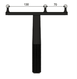
Want Length = 200 mm
Center Distance = 70 mm
Specify these in the Camera Calibration for custom OptiWand in Motive:
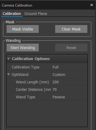
Press “Start Wanding” and start waving the OptiWand in the scene.
Make sure to capture many different positions.
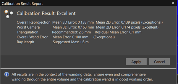
Stop wanding when the software shows green or when around 3000 samples for each camera has been reached. Motive will show a popup indicating whether the calibration was poor or excellent. If poor, then check the measurements of the OptiWand and retry.
Example: The image below shows an “Excellent” alignment
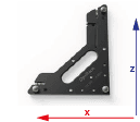
Coordinate Alignment
Coordinate alignment defines the “global reference frame”. This is defined in Motive - and needs to be reflected in Mimic. The usage of Mimic defines this should be done. This section guides you through the needed steps.
Define Ground Plane in Motive
Click “Ground Plane” in the calibration menu.
Place the alignment plate in the scene and press “Set ground plane”.
The global coordinate system has now been defined.
Mimic Specific Remarks
If you are using Track (or both Track and Teach)
Align the ground plane in the same orientation as the robot base frame.
If you are using Teach
For Teach, the ground plane can have different orientations, as this can be used with Reference Frames in Mimic.
Note: The same Frame needs to be created in Mimic as a Reference Frame. Read more about Frames here.
Note: Make sure that Z is in the same direction as the robot. Do this by rotating the ground plane.
Define a Custom Tracking Object (Rigid Body)
In Motive, a rigid body can be defined. This Rigid body will have a pivot point. When used in Mimic, this pivot point will be the "zero point" to measure from when defining the TCP.
In summary, create a Pivot Point by:
Step 1: Place Markers on hardware
Step 2: Define the Pivot Point
Step 3: Move the Pivot Point to desired location
Step 1: Place Markers on Hardware
Place OptiTrack’s reflective Markers on the object that should be tracked.
● When placing the markers, avid symmetry
● Then define rigid body in Motive
See more here.
Place the object in the scene and select all the markers in Motive > Perspective View.
Right click the markers and select > create rigid body. See image below:
![]()
Note: When you right click on the points and click "create rigid body", the body will be defined with respect to the ground plane that you set earlier.
Step 2: Define the Pivot Point
The pivot point of the rigid body is the “zero point” of the Mimic Tracker. This is where you measure from, when defining the Joystick TCP.
The pivot point of the rigid body is the center point, but can be changed. It is recommended to use the Probe Calibration method. See Step 3.
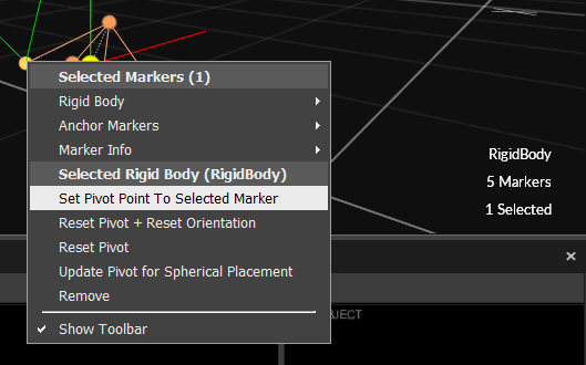
Additionally it is possible to change the pivot point manually or set to one of the markers by:
selecting the rigid body in the perspective view
then Ctrl click on a marker
right click and set pivot point to that marker
see image below:
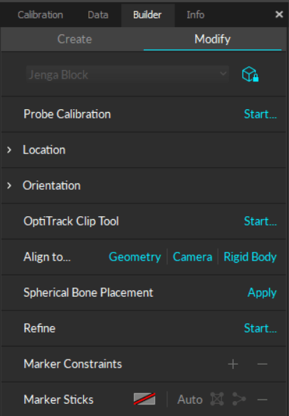
Step 3: Move the Pivot Point to desired location
When Step 2 has been completed, the Pivot Point of the Rigid Body is placed between the identifed markers. This point is likely not easy to use as a reference for TCP calibration. It can be moved manually as described in Step 2, but it is recommended to use Motive's Probe Calibration method.
This calibration method can be found in Motive's Builder Pane > Modify > Probe Calibration > "Start...".
See details: Rigid Body: Modify
Stream Settings
In Motive top bar, go to Edit > Settings > Streaming
Press the three dots and show advanced settings.
Make sure the settings are set up as shown below:
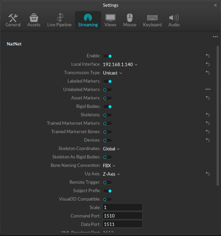
For Mimic Core versions prior to 2.1: set to "Multicast"
For Mimic Core 2.1 or newer: set to "Unicast"
Mimic - How to Setup OptiTrack
Add the Optitrack Tracker in Settings > Tracker
Set as default
![]()
Tracker Settings
The default settings are shown here. Make sure these settings are the same in Motive under “streaming”.
The Server IP Address is the IP address of the server (the Windows PC that is running Motive).
The Client IP Address is the IP address of the client (Controller that is running Mimic).
Read more about smoothing here.
![]()
Once OptiTrack has been setup, the Tracker status is displayed in the top-right corner. Here, it is also possible to see the amount of markers visible.
You are now ready to use OptiTrack as a Tracker in Mimic!
You can now use it with a Joystick. Read more about Joysticks in the Settings section.
Settings
User Levels (password protected)
"User Levels" are available from Mimic Core 2.0.
"User levels" refer to the hierarchical structure used to classify users based on their permissions, access rights, and functionalities within an application or system. These levels help manage and control user interactions and ensure that each user has appropriate access to features, data, and settings.
Important! As the User Level specifies the permissions, it is important to check which is enabled.
2 User Levels are available in Mimic:
Operator
Expert

Operator can select and run previously made recordings and programs.
Expert can create, select and run recordings and programs, as well as managing the Settings.
User Levels can be managed in the top-right corner.
Changing to Expert level requires a password.
Password: "nordbo"
System Settings
Settings is where you tailor Mimic to your setup.
Once you land in Settings, to begin with, you have a description of Mimic Core, its intended use and software version.
On the top right side you can see what kind of Mimic licences you have available. Reach out to our sales team to learn more about licenses: Get in touch
What you can control here:
Network
Configure the network settings of the Mimic Controller.
If preferred, the IP address of the Mimic Controller can be changed through the Mimic software.
Press the “SETTINGS” button from the home page of the Mimic software
Press the “NETWORK” tab from the settings page to enter the network settings page.
Manually configure the IP address by setting the network mode to “STATIC” and enter the desired IP address and subnet mask in the “IP” and “Subnet” fields.
Alternatively, the “DHCP” network mode can be chosen, to let the Mimic Controller receive an IP address automatically. Note that an IP address will only be assigned if a DHCP server is present on the network.
Press the “Save” button in the bottom right corner of the network settings page to apply the settings.
General
1. Choose whether to use an onscreen keyboard or connect an external one.
2. Specify whether outputs should be on when pausing/stopping a program.
3. Enable or disable outputs by default when creating new Recordings.
4. Enable debugging mode. If debugging mode is enabled additional information is provided in log. This is beneficial if edge cases are being tested, and exporting for support.
5. Set language.
External Controls
Enable remote API
Enable different controls of Mimic
Control from Mimic: By default, its Mimic that controls the robot. This means that I can interact with the robot through the Mimic interface.
Control from Robot: Control from robot is more for a production mode. So, the robot can run its code, and when needed, it then calls Mimic.
Launch Nordbo Update Tool
Launches the Nordbo Update Tool directly from Mimic Core.
Robot Settings
Available from version 1.0
Mimic is compatible with a number of different robot brands. On the robot settings page you can add and configure the robots you want to use.
The page provides you an overview of the robots you have available for configuration; here you can mark a robot as default, modify the setup, duplicate or delete it.
The robot settings page guides you through a setup of a robot.
You only see the robots that are relevant to you. This is dependent on the Robot Driver you’ve got. For example, if you purchased Mimic Core for UR, this unlocks drivers for UR robots.
Setting up a Robot
Once you select a robot, you get a preview of the IP address as well as joint and velocity limits. You also have a simulation displaying the robot in the home position (if that has been set up) as well as the parameters for the selected robot.
To add and configure a new robot, first of all, click “Add”, select the robot brand and a model. Here you specify the name for the robot and add a comment if needed. This can come in handy for example when you have a unique setup for an application that requires more constraints on the joint limits.
Enter the IP, to enable communication between Mimic and the robot. There are some robot brands where this step is not needed, for example, Kuka.
Specify the joint and velocity limits. The default limits are from the robot manufacturer, which is also the default in Mimic. These can be changed if your setup requires it.
Example: You may have equipment mounted on the robot, where you would like to limit how much the robot can move in certain joints, to avoid collisions.
Velocity limits define the maximum speed the individual joints can move. In most cases, the default values will be fine.
Once you are done with the setup, you can check the connectivity in the top bar. The robot icon will be red or green depending on whether the robot is connected successfully or not. Green means that you are good to go.
Red can also be okay: Be aware that the robot program can be stopped, hence having no connection to Mimic, until the robot robot program is started again.
Home Position
You also have the option of defining a Home Position. This is a position that you can move the robot to when not in use. You can tick whether to use this feature or not.
From here, you can move the robot to the desired position and save that as a Home Position.
Defining the speed when moving to Home Position
Available from version 2.0
Free Movements, as used for when moving to Home Position can be adjusted in terms of:
Joint velocity
Linear velocity
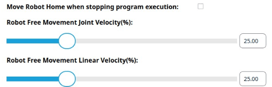
Setting up a Robot
Once you select a robot, you get a preview of the IP address as well as joint and velocity limits. You also have a simulation displaying the robot in the home position (if that has been set up) as well as the parameters for the selected robot.
To add and configure a new robot, first of all, click “Add”, select the robot brand and a model. Here you specify the name for the robot and add a comment if needed. This can come in handy for example when you have a unique setup for an application that requires more constraints on the joint limits.
Enter the IP, to enable communication between Mimic and the robot. There are some robot brands where this step is not needed, for example, Kuka.
Specify the joint and velocity limits. The default limits are from the robot manufacturer, which is also the default in Mimic. These can be changed if your setup requires it.
Example: You may have equipment mounted on the robot, where you would like to limit how much the robot can move in certain joints, to avoid collisions.
Velocity limits define the maximum speed the individual joints can move. In most cases, the default values will be fine.
Once you are done with the setup, you can check the connectivity in the top bar. The robot icon will be red or green depending on whether the robot is connected successfully or not. Green means that you are good to go.
Red can also be okay: Be aware that the robot program can be stopped, hence having no connection to Mimic, until the robot robot program is started again.
Home Position
You also have the option of defining a Home Position. This is a position that you can move the robot to when not in use. You can tick whether to use this feature or not.
From here, you can move the robot to the desired position and save that as a Home Position.
Tracker Settings
Mimic platform is compatible with several tracking technologies. These capture your hand movements in different ways. On the Tracker Settings page, you can add and configure the Trackers you wish to use with Mimic.
Trackers available with version 2.0:
IR Tracker, which enables wireless tracking. This Tracker uses infrared light to track the movements.
FT Tracker, which enables tracking by guiding the robot by hand. This Tracker uses force torque to capture the movement.
OptiTrack Tracker, which enables wireless tracking. Based on OptiTrack. Advanced motion capture technology with high precision and accuracy.
To add a new tracker, press “add”, select the tracker type and “ok”. The newly added tracker gets marked for preview, and depending on which tracker you added, different information is displayed. For example, for IR Tracker, you can preview parameters, such as smoothing, tracker alignment and button states preview, to quickly check if they work correctly. At the same time, on the right side of the interface, in the simulator you can see the tracker TCP in relation to the robot base.
See more about setting up the different Trackers in the next tutorials.
Smoothing
When the tracker captures your hand movements, the noise is captured as well (e.g. a shaking hand). For a smoother recorded path we added a smoothing feature. This averages all the captured points into a more even path.
The values range between 10 and 1000ms.
Note: A greater number results in a more smooth experience. However, it will affect the robot response time - hence you will experience some delay in the movement.
Therefore, we recommend 100 ms.
Tracker Settings - IR Tracker
The IR Tracker allows you to move the robot wirelessly. By the end of this course, you will be able to move the robot like this as shown in the video.
To configure the IR tracker, click the edit icon on the Tracker
Aligning the Tracker with the robot is needed. Follow the on-screen instructions to get the optimum result.
Align the Y-axis of the IR Tracker with the Y-axis of the robot. Make sure the Z-axis is pointing the same way as the robot's Z-axis (if the robot is mounted upright, the Z-axis is pointing upwards). See on-screen instructions for the optimum result.
Note: You will need the Reference Plate for this step.
Aligning the IR Tracker
First of all, we need to align the Tracker and robot. The idea is to use the Tracker to move the robot. So, we want to make sure the Tracker and robot move correctly with each other.
Aligning the Tracker means that you align the Tracker with the robot, so that they are “looking” the same way. So, when you move "forward", the robot moves "forward".
Tracker alignment defines how well the robot follows the joystick as you demonstrate a movement. That's why this step is very important.
A more precise alignment will result in a better relation between the hand movement and the robot movements.
Read more below to learn how to obtain a good alignment.
Step by Step
The robot navigates in space by a coordinate system: X, Y and Z. These are what we are aligning the Tracker with.
Step 1.
To align the Tracker, first of all, place the Reference Plate in relation to the robot.
X, Y and Z vary between robot brands. You can see these in Robot Settings where the specific robot models are shown in a simulation.
See examples of the UR and NACHI below.
Aligning with the UR Robot
X is red
Y is green (same direction as the power cable from the robot base)
Aligning with a NACHI
(MZ07 as an example)
X is red
Y is green

Note: In the video we are using a UR robot, 45 degrees angle, therefore we use the wire from the robot for guidance and align the calibration place accordingly.
Step 2.
Align the Y-axis of the Reference Plate with the Y-axis of the robot.
![]()
Step 3.
In Settings > Tracker > IR Tracker Press "Align".
Important: When aligning, it is important that there is line of sight between the Tracker and the Lighthouse as this can break the tracking.
Note that if you moved the Lighthouse you need to perform this task again.
Validating the Alignment
Note: This is illustrated in the video of this tutorial.
Now that it has been aligned, we want to validate that we calibrated it correctly.
When it comes to the IR Tracker, after you did the tracker alignment, you can go into Track and move the tracker along one of the robot's axes to see if the robot moves along the same axis in the simulation. You can check rotations by rotating the joystick and see of the robot like you do.
You can also go into the Creators page by selecting Track, move the joystick along the robot's different axis one at a time and validate that it moves correctly.
You can also go into the Creators page by selecting Track, lock orientations, move the tracker along the robot's different axis one at a time and validate that it moves correctly.
Once you are confident that on the high level the IR tracker calibration seems okay, you can make a more precise test by following a straight line / or tracking an object and seeing if you and the robot do the same. Make the test for two perpendicular lines.
In the case that it did not work, it is very likely that the Reference Place has been placed in an unintended orientation.
Example: You observe that the robot moves to the right, when you move forward (90 degrees difference). This is likely because the Reference Plate has been placed 90 degrees off while aligning. The plate can turned 90 degrees and the Tracker can be realigned.
Smooth Duration
You can also adjust the Smooth Duration of the Tracker. It is a feature that averages out the captured recorded path so it runs smoother. To learn more about it you can watch a dedicated video about smoothing.
Tracker Settings - FT Tracker
Note: In Mimic Core 1.1 the FT Tracker is available for Universal Robots.
The FT Tracker enables you to guide the robot by hand.
To configure the FT Tracker, click the edit icon.
Make sure the IP of the FT Tracker is on the same subnet as the Mimic Controller.
Align the Y-axis of the FT Tracker with the Y-axis of the robot. Make sure the Z-axis is pointing upwards. See on-screen instructions for the optimum result.
Validating the Calibration
You can validate the FT Tracker calibration by taking a look at the simulation and checking if the position and orientation in the simulation are matching. This is a live view so you can see if the orientation of the FT sensor relative to the robot base matches the current orientation on the physical robot.
Smooth Duration
You can also adjust the Smooth Duration of the Tracker. It is a feature that averages out the captured recorded path so it runs smoother. To learn more about it you can watch a dedicated video about smoothing.
Tracker Settings - SIM Tracker
The SIM Tracker is a simulated Tracker that can be used to move the robot with a keyboard (both in simulation and the physical robot). Here you can configure keyboard buttons to control the simulated robot and a physical robot.
The Tracker is made for development purposes, to allow for testing in a simulated environment.
Keyboard buttons can be connected to controlling positions in terms of X, Y Z, RX, RY and RZ.
Bt1, bt2, bt3 are Tracker outputs.
Note: The simulated Tracker is only available with the Generic Driver (requires a license).
Joystick / Tracker Mount Settings
Available from version 1.0
Overview
Mimic can capture my hand movements and transfer them to the robot. This means that we need something to capture that Mimic can capture. That is what our Joysticks do - we move the joystick and the robot follows along.
The buttons have standard functions. If you want to rearrange what the buttons do, we have a separate tutorial on that (see our tutorial on I/O Mapping).
In Mimic Core version 1 this is referred to as "Joysticks".
In Mimic Core version 2 this is referred to as "Tracker Mount".
![]()
We control the Tool Center Point (TCP)
What it is: The Joystick is defined by a TCP - Tool Center Point. That is what the robot navigates after. Similarly, the robot has a TCP - by default it is the center of the flange. In this case we have mounted one of our Pointers (this could also be a tool). So, now that TCP is the tip of the Pointer [highlight], just like on the joystick.
So, when I control this point on the joystick , this is the point I control on the robot. The Standard IR Joystick is designed as a pencil, allowing you to draw a line with that point.
In this sense, a joystick is simply a point that I control.
On the joystick settings page you have an overview of all your joysticks. If you select one, you get a preview of the joystick and its calibration values for position and rotation. On the right side of the interface you also see the relation between the Tracker and the joystick TCP visualized.
Each joystick on the list lets you set the joystick as default, edit, duplicate or delete it. If you set something as default, this will be what is preselected for you, when recording.
You will have all standard joysticks available. If that is what you want to use, set that as a default. Then you are good to go.
You also have the option of making a custom joystick. Maybe you want the joystick to look more like the tool you have, or you want to mount it directly on the tool.
If you want to use a custom joystick, you can create that. Watch our dedicated video on that subject. (see our tutorial on Custom Joysticks).
You can read more about TCPs here.
Items
Items allow for adding 3D items in the simulation.
Items are CAD files that can be used for:
Visual representation in simulation
Collision check
Collision check is based on collision between CAD geometries or TCPs.
Items can be modified in terms of:
Position
Rotation
Hence, making it possible to import an existing/prepared CAD file to Mimic and place and orient it as needed.
Note: CAD files has zero-points predefined. Mimic uses this zero-point as a basis for moving the file in simulation. Before importing CAD files into Mimic it is recommended to set a zero-point in the CAD files that makes it easy to manage it in Mimic. Mimic does not allow for manipulation of zero-points.
Requirements for CAD items
Format: STL
File size formatting: Max 10 MB for the complete workcell (above will affect performance). Reduce individual file sizes if needed
File name and and file: No Chinese characters
Joystick / Tracker Mount Settings - Custom Joystick
Available from version 1.0
Overview
In Mimic Core version 1 this is referred to as "Joysticks".
In Mimic Core version 2 this is referred to as "Tracker Mount".
Often custom joysticks bring a lot of value. Let’s say you want to make the standard joystick look more like the tool you have on your robot, or you want to mount the Tracker on an actual tool, then you can create that in Mimic. By the end of this course you will be able to use Mimic with custom joysticks.
It is important with a good calibration of the joystick to get the correct "translation" between the movements of the joystick and Tracker and the movements of the tool on the robot.
Essentially, we are calibrating a TCP (you can read more about TCPs here) - the point on the joystick that we want to control. So we need to select a point that makes sense to control.
To add a new joystick, press add, which takes you to a new page. Start out by giving it a meaningful name and adding a comment if needed. For example, name: standard joystick, comment: for demonstrations.”
For the complete setup of the joystick, we need to calibrate both position and rotation.
How to Calibrate
Guidance for performing calibration is provided directly in the interface.
2 calibrations are needed:
Position
Rotation
Position calibration
Position is calibrated by setting 4 points.
The position of the point must be the same, but the orientation of the 4 points must be the same. This means that the joystick should point at the same point for all 4 points, but at different orientations (angles).
The closer the positions from the 4 positions are, the more precise it will be.
Important:
The less difference in position between the 4 points, the better TCP.
The greater the difference in rotation between the 4 points, the better TCP.
Rotation calibration
Rotation is calibrated by:
Defining the origin of the Frame (coordinate system)
Defining the positive x-axis of the robot
Defining the positive y-axis of the robot
The more precise this is performed, the more precise the calibration will be.
If in doubt of the robot's coordinate system: Go to Settings > Robot > Select the robot, see the axis in simulation.
Example:
NACHI robot with X and Y.
Example of Nordbo Robotics custom joystick
Painting Spray Gun
OEM Mount - Fake Spray Gun (Beta) | 3D CAD Model Library | GrabCAD
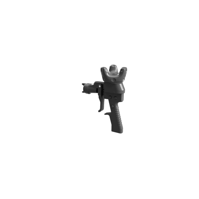
Application Demo Kit for IR Tracker
These are extensions that can be mounted to the IR Standard Joystick, to simulate various surface treatment tools.

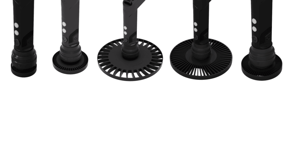
Robot Tool Settings
In Mimic Core version 1 this is referred to as "Robot Tool".
In Mimic Core version 2 this is referred to as "Robot Mount".
A robot knows where it is. So it won’t collide with itself. However, it cannot see anything, so as soon as we mount a tool on the robot, we have to tell the robot where the tool is.
The robot tool is defined by a TCP - Tool Center Point. By default, it is the center of the flange.
The joystick also has a TCP. These are correlated, so, when we control this point on the joystick, this is the point I control on the robot.
(you can read more about TCPs here)
It is highly recommended to have a robot tool and joystick/hand tool that are very alike. If you are painting with a specific paint gun, it is easier, if a similar paint gun is on the robot. The same goes for a sanding tool.
Robot Tool settings, allows you to configure the tools that are mounted on the robot.
To add a new tool, click the “add”
Name the Tool with a meaningful name
Optional: Add a descriptive comment to specify the tool further
Use the calibration wizards to calibrate the position and orientation of the tool . See specific calibration wizard guidelines.
Note: If using the standard Robot Pointer, the height = 50 mm. Hence, the TCP of a robot mount with only this Pointer is Z = 50.
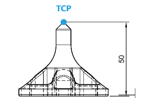
How to Calibrate
Guidance for performing calibration is provided directly in the interface.
2 calibrations are needed:
Position
Rotation
Position calibration
Position is calibrated by setting 4 points.
The position of the point must be the same, but the orientation of the 4 points must be the same. This means that the tool should point at the same point for all 4 points, but at different orientations (angles).
The closer the positions from the 4 positions are, the more precise it will be.
Important:
The less difference in position between the 4 points, the better TCP.
The greater the difference in rotation between the 4 points, the better TCP.
Rotation calibration
Rotation is calibrated by:
Defining the origin of the Frame (coordinate system)
Defining the positive x-axis of the robot
Defining the positive y-axis of the robot
The more precise this is performed, the more precise the calibration will be.

CAD File
(Available from 2.0)
It is possible to add (import) and remove a CAD file of the robot mount.
CAD files can be calibrated in terms of Position and Rotation.
The CAD file can be used as a visualized representation and for check of collision.
Note: CAD files has zero-points predefined. Mimic uses this zero-point as a basis for moving the file in simulation. Before importing CAD files into Mimic it is recommended to set a zero-point in the CAD files that makes it easy to manage it in Mimic. Mimic does not allow for manipulation of zero-points.
The CAD file will be used in the Simulator in Creator, when moving the Joystick Mount / Joystick around, to visualize where the mount will be.
Requirements for CAD items
Format: STL
File size formatting: Max 10 MB for the complete workcell (above will affect performance). Reduce individual file sizes if needed
File name and and file: No Chinese characters
I/O Mapping Settings
Available from version 1.0
I/O Mapping page allows you to set up inputs and outputs from Joystick, Robot and other external devices.
I/O Mappings are split into two sections for a better overview:
Functionality
Outputs
Functionality allows inputs from the tracker and robot to be mapped to Mimic functionality or outputs on the robot.
Example: map "Move" and "Play/Pause".
Outputs allows you to map inputs to outputs. Example:
Map an external button to turning on a tool.
Workcell Settings
When we work with robots, often they are supposed to work with a certain space - within the size of a table or a cell that it is placed in. This is for safety measures, to make sure the robot does not collide with anything. Such a space we are able to define in Mimic - we call it a workcell.
Workcells limits the robots workspace in order to prevent collisions. Essentially, we define a box that the robot can move within, but not move outside.

The Workcell page allows you to configure the Workcell.
Workcells limits the robots workspace in order to prevent collisions.
Set up a workcell by providing “Box dimensions” and corner positions.
Specify the dimensions of the workcell box.
Specify the corner position. Measure this from the robot base.
Items
Items allow for adding 3D items in the simulation.
Items are CAD files that can be used for:
Visual representation in simulation
Collision check
Collision check is based on collision between CAD geometries or TCPs.
Items can be modified in terms of:
Position
Rotation
Hence, making it possible to import an existing/prepared CAD file to Mimic and place and orient it as needed.
Note: CAD files has zero-points predefined. Mimic uses this zero-point as a basis for moving the file in simulation. Before importing CAD files into Mimic it is recommended to set a zero-point in the CAD files that makes it easy to manage it in Mimic. Mimic does not allow for manipulation of zero-points.
Requirements for CAD items
Format: STL
File size formatting: Max 10 MB for the complete workcell (above will affect performance). Reduce individual file sizes if needed
File name and and file: No Chinese characters
Components Settings
Available from version 1.1
The Components page allows you setup external components to work with Mimic.
The following components can be configured:
Conveyor
This allows you to configure Mimic to run with conveyors.
Trigger
This allows you to enable what can be triggered by an external trigger.
NAC
This allows you to enable force feedback when using Nordbo Robotics' NAC (active compensation unit).
NAC2
This allows you to enable force feedback when using 2x Nordbo Robotics' NAC (both "NAC" and "NAC2" must be enabled)
URForce
This allows you to enable force feedback when using the build in force sensor in UR robots.
URACU
This allows you to enable force feedback when using Nordbo Robotics' NAC (active compensation unit). This is a Universal Robots specific solution that can be enabled via a Script.
Conveyor
Note: To use the Conveyor functionality, the Nordbo Conveyor Interface is needed. Read more about the Nordbo Conveyor Interface here.
The Nordbo Conveyor Interface communicates directly with Mimic, not the robot. Hence, it is independent from the robot and robot brand.
Conveyor can be configured in terms of:
Enabling/disabling the conveyor component
Enabling/disabling the program to stop, when the conveyor stops
Enabling/disabling the program when the conveyor runs in reverse
Specifying the amount of ticks per meter (see more below)
Specifying the minimum speed of the conveyor (m/s).
Default is set to 0.0010 m/s (1 mm/s).
Specifying the backwards threshold in (mm) before defining it as a reverse motion
Defining the direction of the conveyor by defining 2 points with the robot (see more below)
Specifying the amount of ticks per meter
If the amount of ticks is unavailable from the supplier's documentation, the amount can be estimated by:
Reading the current tick count
Let the conveyor run for a specified length
Read the the new current tick count
Subtract the two tick counts and divide by the length
Defining the direction of the conveyor by defining 2 points with the robot
The direction of the conveyor can be defined using the robot.
On the conveyor page, you can define 2 points. The direction is defined from Point 1 to Point 2.
These points are defined by X, Y and Z.
Additional option for Universal Robots only: Setting up scripts on the UR robot
UR robots are compatible the Nordbo Conveyor Interface.
Additionally, Mimic's conveyor functionality can be utilized by using the conveyor functionality on the UR. In order to use the conveyor, a script must be setup in the robot program.
The script can be found on the USB provided in the packaging: v1.1.0 > mimic-1.1.0-robot_code > UR > components > mimic_conveyor_socket.script
On UR, these must be placed in "BeforeStart".
The following must be adapted to the use:
local encoder_index = 0 # Index of the encoder to define. Must be either 0 or 1
local decoder_type = 0 # 0: No encoder
# 1: Quadrature
# 2: Rising and Falling
# 3: Rising edge
# 4: Falling edge
local encoder_input_A = 0 # Encoder input A pin. Must be 8-11 for E-Series, 0-3 for CB-Series
local encoder_input_B = 0 # Encoder input B pin. Must be 8-11 for E-Series, 0-3 for CB-Series. Only for quadrature encoder
Trigger
Trigger allows you to enable what can be triggered by an external trigger.
Trigger can be configured in terms of:
Enabling/disabling the trigger component
Enabling/disabling triggering of Teach
Enabling/disabling triggering of Track
Enabling/disabling triggering of Play
Setting up scripts on the robot
In order to use the trigger, a script must be setup in the robot program.
Example: Universal Robots
The script can be found on the USB provided in the packaging: v1.1.0 > mimic-1.1.0-robot_code > UR > components > mimic_trigger_socket.script
On UR, these must be placed in "BeforeStart".
NAC and URForce
The Force Control feature needs an external component to adjust the force to. There are three options:
NAC (Nordbo Robotics' active compensation unit)
URACU (Nordbo Robotics' active compensation unit, Universal Robots specific)
URForce (the built in force sensor in UR robots)
These can be enabled disabled on their pages.
Setting up the NAC on the robot for Force Control
Make sure:
the NAC is connected. You can find the User Manual for the NAC here.
the NAC URCap is installed and enabled.
2 options are available for using NAC for force control:
Option 1: using the "NAC" component directly in Mimic Core
Option 2: using the URACU with a script on Universal Robots.
Both options work for all supported robots.
Option 2 is only an option on Universal Robots. Option 1 is also compatible with Universal Robots.
Option 1: When using the "NAC" component:
Enable the "NAC" in Settings > Components
Set the IP of the NAC (read more here)
Auto calibrate tool weight
Option 2: When using the URACU (only an option on Universal Robots):
In order to use the NAC, a script must be setup in the robot program.
The script can be in the robot code folder (you can get the latest via the Nordbo Update Tool). E.g.: v1.1.0 > mimic-1.1.0-robot_code > UR > components > mimic_acu.script
On UR, these must be placed in "BeforeStart".
Setting up 2x NAC on the robot for Force Control
If the tool unit contains 2x NAC, it is possible to control these through Mimic Core.
To use the 2x NAC, make sure:
Both "NAC" and "NAC2" components are enabled
Both "NAC" and "NAC2" components have IPs set (read more here).
Note: Both NACs will execute with the same force, simultaneously.
Frames Settings
Depending on the case you are working one, you may need to create frames.
Frames are fields with specific placements that the robot uses to know where it is and where to go. Think of them as pieces of paper, that we can define in different places at certain angles. Hence, they consist of:
Position
Rotation
(Frames are measured from the base of the robot.)
These can be defined with the Calibration Wizard or manually (by measuring from the robot base to the desired frame).
X, Y and Z modifies the position
RX, RY and RZ modifies the orientation
Usage of Frames
Frames can be used as:
Generic frames and can be used for locking movements in Track.
Planes can be used for restricting robot movements when aiming for higher precision. For example, you can lock robot movements to a plane.
Teach Frames are used for Teach and specifies where the recorded Trajectory will be executed in relation to where it was recorded.
How to add
To add a new Frame, click the “Add”
Use the Calibration Wizard to calibrate the Frames or measure manually.
See specific calibration wizard guidelines in the video.
How to Calibrate: 2 Options
2 options are available for calibration of frames:
Option 1: Standard calibration
Option 2: Custom calibration
Standard calibration can be achieved using the Reference Plate in the kit - or by defining 1) Origin, 2) positive X and 3) positive Y axis, using the robot.
Custom calibration can be achieved by using custom calibration pointers, the robot and the Tracker.
When defining the positive X and Y axis with the robot, it is recommended to use the robot to jog in the exact direction (given that the robot is mounted to allow for such).
Note:
Position the Reference Plate/Frame close to the workpiece if possible. This will mitigate accuracy challenges.
The IR Tracker needs to be in view of the Lighthouse when performing Teach Calibration (a calibration that is required for the IR Tracker, before Recording)
Option 1: Standard Calibration
Create frames by providing 1) Origin, 2) positive X and 3) positive Y axis point data, using the robot. The Reference Plate can be used as a guide.
A pointy element on the robot is recommended to ease the work. The Robot Pointer in the package can be used.
You can copy and offset workspaces by duplicating Frames and recalibrating them to a new position.
Note:
It is the Tool TCP that is used when defining Frames, so make sure you have the right tool selected.
The precision of the calibrated Frame is dependent on the precision of the defined origin, positive X and positive Y axis.
Option 2: Custom Calibration
Some workspaces requires a custom calibration. In these cases, custom calibration can be made.
Several points can be defined. Minimum 4 points are needed. More points will result in a more precise calibration.
Needed for custom calibration:
Custom pointers to place in workspace
Pointers on the robot (e.g. the Robot Pointer in the kit)
Robot
Tracker and Tracker Mount/Joystick
Important: make sure to be able to replicate the excat pointer position, to make potential future recalibrations faster.
How to:
Place the pointers in the workspace. Make sure they cover as much of the workspace as possible
For each point, bring the robot pointer and the Tracker Mount/Joystick to the pointer
(this can be done in sets ; or first all robot points, then Joystick points ; or first all Joystick points, then robot points)
Repeat for min. 4 points. Adding more will result in higher precision.
Calibrating a Reference Frame for Improved Accuracy
The steps provided in this section guides you through calibrating a Frame for improved Accuracy.
The steps guides you through testing the existing Frame, making a series of recordings to review the accuracy, then adjusting them.
These recordings are created in Teach.
If you are using the standard components provided in the Tracker kit:
- Make sure to select the pointer as default
- Make sure to select the IR Standard Joystick with Pointer as default
If using custom hardware (Joystick and Robot Tool)
- Make sure that both are set as default
- Make sure to use their TCPs as the guiding point for the exercises below.
Defaults can be set in Settings. and are displayed with the icon:

Steps to perform
First Recording: Linear Movement in Positive Y
Make sure that you can check the relation between the recorded path and the path executed by the robot (e.g. by marking it with a marker, or placing a linear item)
Create a recording a linear movement in the positive Y direction. It is recommended to create a path with a long distance, as deviations from the intended line will be more significant.
Ensure that the Joystick TCP is oriented perpendicular to the surface tested against.
Review the Recording
If the recorded line is not followed by the robot, return to the reference frame calibration.
Correct the orientation by applying the offset discovered.
Repeat until satisfying result has been achieved.
Second Recording: Linear Movement in Positive X
Repeat the steps from the previous section.
Using Mimic
The Creator 2.0
When in Track, Teach, Edit or Play, a control panel is available. This control panel provides the basic Mimic functionality for moving the robot, recording and playing recordings. Depending on which Mimic functionality used (Track, Teach, Tune or Play), different options will be available.
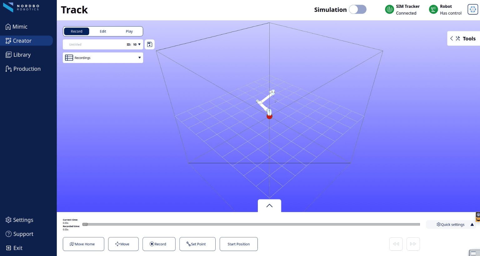
In Record
Move Home
Moves the robot to the Home Position (defined in Settings)
Move
Allows you to move the robot with the used Tracker and Joystick
The “Move” button can be released and clicked at any time during programming to stop/continue the tracking of movements while recording. When the “Move” button is released, the recording will pause until the button is pressed again.
Make sure the joystick TCP is aligned with the robot TCP before moving.
Move is only present in Track, not Teach.
Record
Allows you to record the movements made
Set Point
Allows to to make point-to-point based paths
Start Position
Makes the robot go to the start position of the
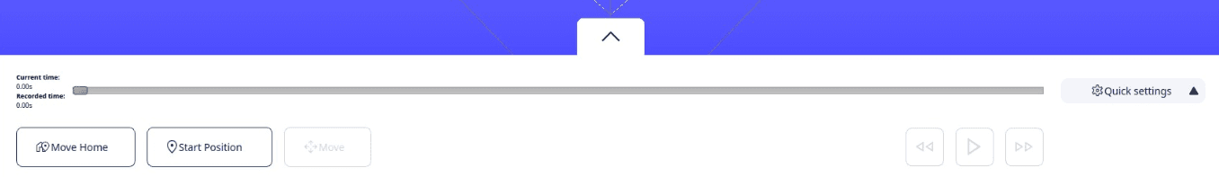 Control Panel (collapsed) from Record screen
In Edit
Backward
Allow you to wind backwards in a recorded program.
Note: that backtracking and recording a new movement will overwrite the Trajectory recorded after this point.
Forward
Allows you to wind forwards in a recorded program.
Undo/redo Edits
Allows you to undo/redo latest Edit.
Reset all Edits
Allows you to remove all Edits.
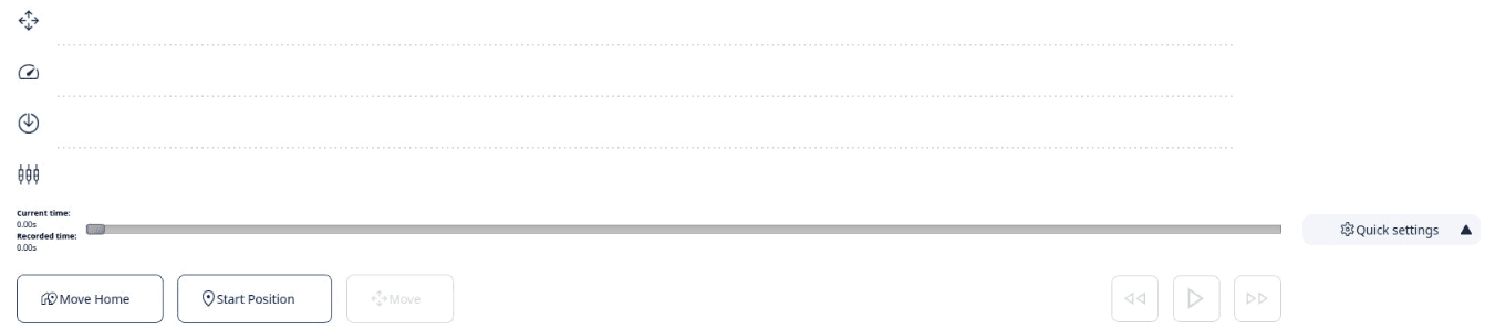 Control Panel (expanded) from Edit screen
In Play
Plan
Plans the recorded path for robot to Play.
(pre-requisite for robot to play)
Play
Plays the planned path.
Stop
Stops an ongoing path.
The Options Panel
The Options Panel can be expanded to reveal extra features that can help you modify the recorded path.
The Options Panel can be expanded and collapsed at all times.
Read more about features in the Editing a Recording 2.0 section.

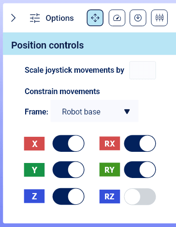
Simulation
Simulation can be used to preview a recording in the interface, prior to running it on the robot.
Simulation can be enabled with the toggle "Simulation":

The simulator can contain items (3D files) in the workcell and robot mount and can check for collision.
Collision check is based on collision between CAD geometries or TCPs.
Once in Simulation, the background changes color to light blue:
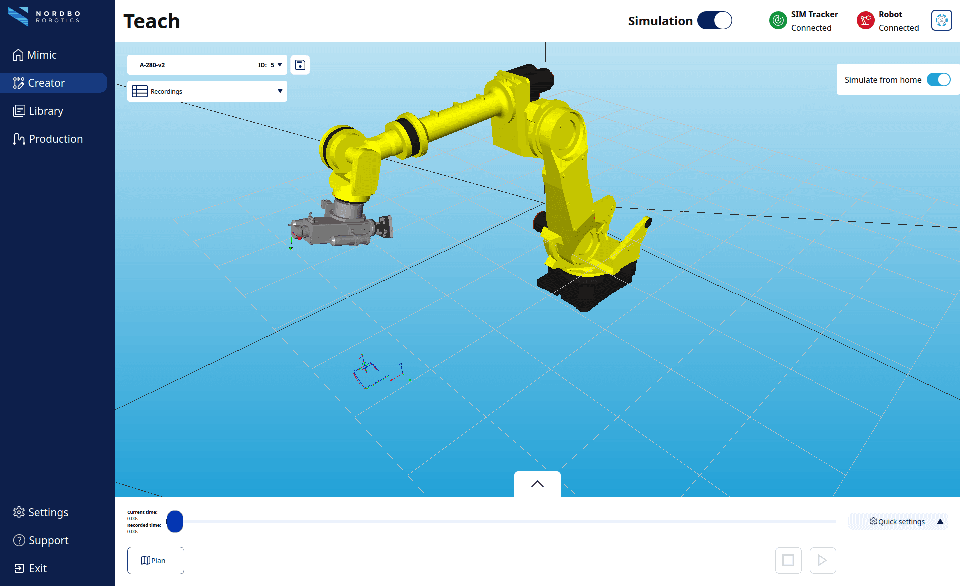
Quick Settings
Quick settings allows you to
Playback speed
Allows you to set the wind speed.
Note: This does not change the actual speed of the recording.
Enable/disable outputs
Allows you to specify whether recorded outputs are active or not when Playing.
Recordings - Pause your recordings
Recordings can contain "sub-recordings". "Sub-recordings" are separate paths that stacks together to one complete path, a recording.
These are used differently in Track and Teach.
This essentially allow you to "pause" a recording.
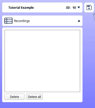
Track
In Track, the amount of sub-recordings created is related to the amount of start/stop of recordings created and amount of "Move" used.
Example:
Start recording > Move > Stop recording > Start Recording > Move > Stop Recording = 2x sub-recordings
Start recording > Move > Move > Move > Stop recording = 1x sub-recording
Teach
In Teach, the amount of sub-recordings created is related to the amount of start/stop of recordings created.
Example:
Start record > stop recording > start recording > stop recording = 2x sub-recordings
Start record > stop recording = 1x recording
File and Setup Management
Expanding the file management allows you to:
Rename the recording
Create a new recording
Change settings used
By default, these will be set as the defaults set in Settings. If needed, it is possible to change to other defined options.
It is possible to change:
- Tracker
- Tracker Mount / Joystick
- I/O Mapping
- Robot Mount / Robot Tool
- Reference Frame
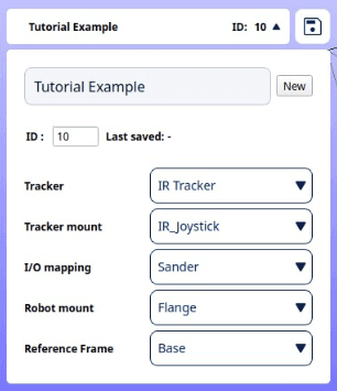
Editing a Recording
Edit is meant for modifying and perfecting the captured movements in a recording. Edit can be used for recordings made with both Track and Teach.
In Edit, you can modify:
Position

Force

Speed

Outputs

Edit Position
You can review the recording and make changes in the position by using "Move".
To make a change in position, hold "Move" and move the Joystick.
Mimic offers features that can make it easier to make the desired edit in position. These are:
Scale recorded movements - The movements of the Joystick can be scaled by specifying a scale. A higher number means the robot moves faster relative to the Joystick.
Example: With a scale set to 2.0x, the robot will move 20 cm when the Joystick moves 10 cm.
Be aware that increasing the scale above 1.0x will make the robot more difficult to control as its movement will be faster than the user’s.
Constrain robot movements - Lock one or more axis of movements (X, Y, Z and RX, RY, RZ) for the robot by switching them on/off.
They will be locked relative to the feature selected in the combo box.
Movements can be constrained based on:
- Robot Base
- Robot Mount / Robot Tool TCP
Examples
Example: Edit the position of a recording, from a specific point and for the rest of the recording.
Enter Edit
Click "Start position" to automatically move the robot to the starting position of the recording
Press and hold "Forward" or "Backward" to scroll through the recording (Default: the 2 white buttons on the IR Standard Joystick)
Edit position in the recording in the “Position” tab, by holding the “Move” button and moving the robot (Default: the side button on the IR Standard Joystick)
Example: Edit the position of a recording, in a specific interval.
Video coming soon
Enter Edit
Click "Start position" to automatically move the robot to the starting position of the recording
Specify the interval
Press and hold "Forward" or "Backward" to scroll through the recording (Default: the 2 white buttons on the IR Standard Joystick)
Specify the first point of the interval, by Pressing "Move" (without moving the joystick).
Press and hold "Forward" or "Backward" to scroll through the recording
Specify the second point of the interval, by Pressing "Move" (without moving the joystick).
Edit the position
Press and hold "Forward" or "Backward" and scroll the intended place in the interval
Edit position, by holding the “Move” button and moving the robot
Edit Force
It is possible to specify the specific force applied (in Newton).
To apply or edit the applied force,
Go the the desired starting point in the recording
Specify the force
Toggle on "Override"
Go forward through the section you want to have the force applied in
Toggle off "Override"
"Enable robot adjustment" allows for toggling on/off whether the robot moves when using compensation units (such as the Nordbo Active Compensation Unit, NAC) or not.
"Override whole trajectory force" allows you to override the entire trajectory/path with the specified force.
Edit Speed
Several options for editing speed is available:
Speed scale
Enables scaling of speed, while maintaining the speed pattern. E.g. if the scale is set to 2, the recording will run with speed x2.
Override robot speed
Allows for setting a constant speed. If speed is set to 100 mm/s, the robot will run with excatly 100 mm/s in the selected area.
To edit to a constant speed,
Go the the desired starting point in the recording
Specify the constant speed
Toggle on "Override robot speed"
Go forward through the section you want to have a constant speed in
Toggle off "Override robot speed"
Set max speed
Allows for setting a max speed that the robot is allowed to move. Can help avoid scenarios where the robot cannot follow the speed of the recording.
Edit Outputs
To override outputs in a desired interval:
1. Press the "Override outputs" toggle and select which outputs should be active.
2. Move Forward and Backward to set a desired point.
3. Press the "Override Outputs" toggle again. The outputs have now been changed in the interval between the two points.
Library
Library stores all your previously created Recordings and Programs. Programs are collections of Recordings. These can be Played from the Library or Edited.
The User Level selected defines what can be achieved.
The lowest user level can select and run recordings and programs.
The highest user level can create, edit and run.
Read more about User Levels here.
Select and Run
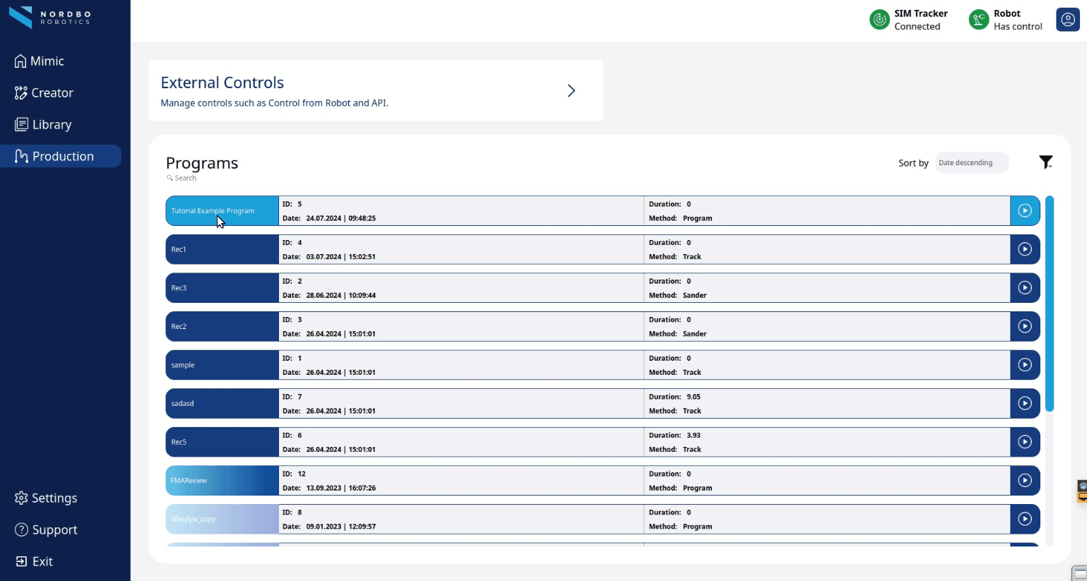
Manage and Create
A Program is a collection of recordings and their repetitions intended for building more complete surface treatment (grinding, sanding, polishing) processes. To build a new Program, select one Recording at a time and drag it into a program.
Both Recordings and Programs have Unique ID numbers.
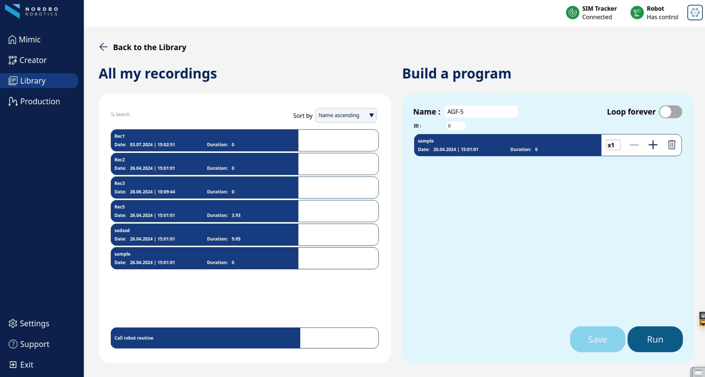
Call robot routines from Mimic
It is possible to define programs on the robot and then call them directly from Mimic.
Examples of robot routines can be:
Home Position
Call another component
Call an abrasive change
This feature uses predefined programs from the robot. These needs to be defined with registers.
How the registers are defined on the robot, is robot dependent.
Please check documentation and requirements with your robot brand supplier.
How to implement robot routines
Note: in Mimic Core 2.0-Beta, this functionality is available on on UR and FANUC robots.
In Library, when making a program, in the column "All my recordings", the "Call robot routine" is always available:

Drag the "Call robot routine" module to the program structure.
Assign the ID of routine, defined in a register on the robot
(in the example below, the ID is set to 1)
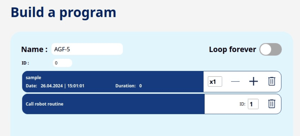
In this example, the program will first run the recording "sample", then run robot routine with ID 1.
It is possible to have several robot routines in the same program. Example:
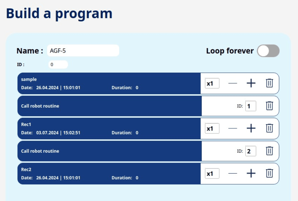
Support
Mimic Core contains an integrated support page. This page serves several purposes:
There is a link directly in Mimic to this Workshop where all guiding materials and documentation is.
(This requires an internet connection)
There is an "About" with system details. It is possible to export this or copy to clipboard.
For support purposes, it is possible to export "Support Data". This is to ensure the best support, especially if it has been experienced that Mimic crashes.
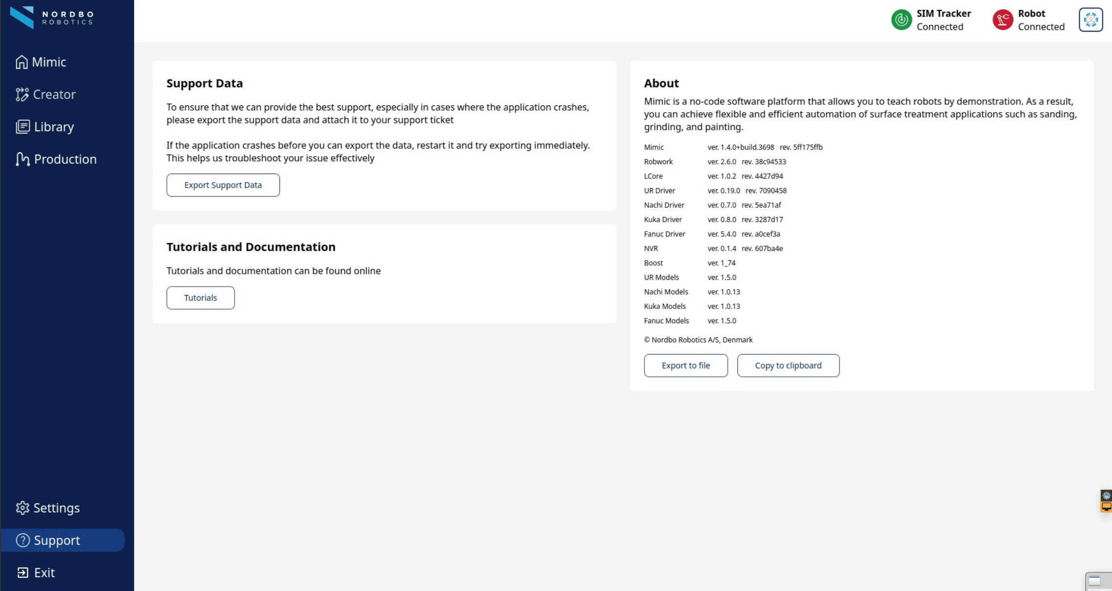
FAQ
Why does the tracking sometimes become imprecise or noisy when using the IR Tracker?
If the tracking becomes imprecise or noisy, it could be one of multiple reasons, depending on the Tracker used. Please see the Tracker manual for more info.
Why is Mimic unable to connect to the Tracker?
If Mimic is unable to connect to the Tracker, please check or do the following:
Check that all cables are properly connected.
Check that the Robot IP is set correctly.
Check that the Tracker IP is set correctly.
Make sure that only one robot or computer is connected to the Tracker.
Restart the Tracker.
Restart the UR Robot.
Please see the Tracker manual for more info.
I made a good Mimic recording, and I want to use this recording with an offset. How can I do it?
Copy you original recording → Open the copied recording → Change the first position of the recording with the offset that is required → save the program.
Does Mimic Core require a Blue License Key for use in Mimic UR?
No, Mimic Core does not require any physical license key.
Can other compensation units, aside from NAC, integrate with Mimic and offer force setting options?
Customization in this regard requires expertise; for more information, contact Nordbo Robotics.
Does Mimic control external robot axes like 7th axes, 2-axis positioners, and 3-axis positioners?
Mimic can be used with external robot axes as a standalone function.
Can the IR Tracker switch to the FT Tracker on the same Mimic Core Controller?
Yes, the system can switch between the any Trackers on the same Controller.
Is Mimic Core compatible with UR20/UR30?
Compatibility with UR20/UR30 requires testing with PolyScope 5 and the kinematics model of UR20/UR30
How can support be obtained from Nordbo Robotics for any issues?
Support can be accessed through the helpdesk at https://nordbo.io/helpdesk.
When using the "Conveyor" feature with Mimic Core, how do you do the teaching?
To teach the system, initiate recording while the conveyor is in motion. Mimic will save this recording with the robot speed synchronized to the conveyor speed during the recording.
Subsequently, you have the option to increase the speed of the conveyor, and Mimic will adjust accordingly, allowing the robot to move faster to match the conveyor speed.
Can the Lighthouse be moved after calibration while in a powered-on state?
The Lighthouse should only be moved in a powered-off state.